
Screwdriver with torque setting mechanism

a technology of torque setting mechanism and screwdriver, which is applied in the field of screwdrivers, can solve problems such as screw damag

Inactive Publication Date: 2007-02-22
WANG CHUN FU
View PDF1 Cites 89 Cited by
  • Summary
  • Abstract
  • Description
  • Claims
  • Application Information

AI Technical Summary

Benefits of technology

[0005] It is therefore an object of the present invention to provide a screwdriver comprising a rotatable handle including a sleeve including an internal lower elastic member, a support ring urged against an internal shoulder by the elastic member, the support ring including a plurality of male members equally spaced around its upper surface, and a scale window on a surface of the handle; and a torque setting mechanism including an actuation rod passed the support ring and the elastic member and including a lower threaded section, an upper threaded section, two opposing intermediate flats extended from the upper threaded section to the lower threaded section, and a top socket for securely receiving one end of a shank; a clutch ring put on the flats and having a plurality of equally spaced female members formed on its lower surface for receiving portions of the male members; a torque adjustment ring rotatably provided on tops of the clutch ring and the handle with the actuation rod passed, the torque adjustment ring urged against a shoulder between the upper threaded section and the socket; a lower torque adjustment nut threadedly secured to the lower threaded section and provided under the slee

Problems solved by technology

It is understood that in one case the screw may be damaged if force (i.e., torque) exerted thereon exceeds a set value thereof.

Method used


Image

  • Screwdriver with torque setting mechanism
  • Screwdriver with torque setting mechanism
  • Screwdriver with torque setting mechanism

Examples


Embodiment Construction

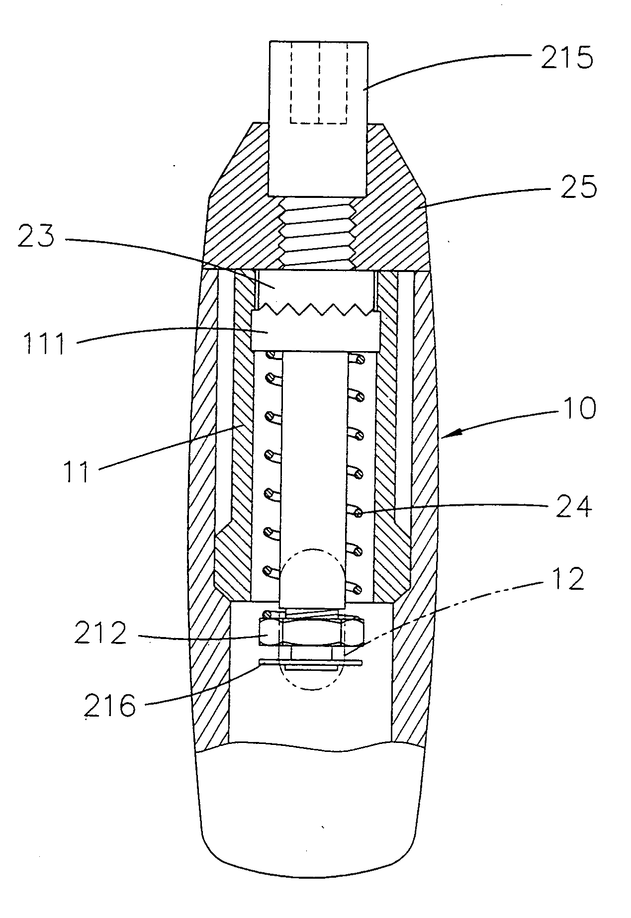
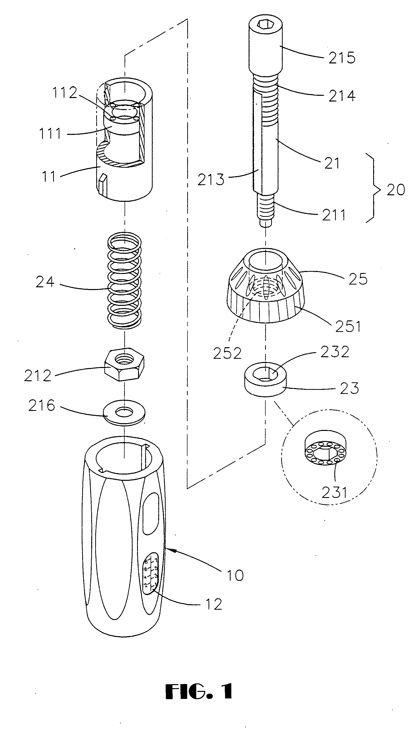
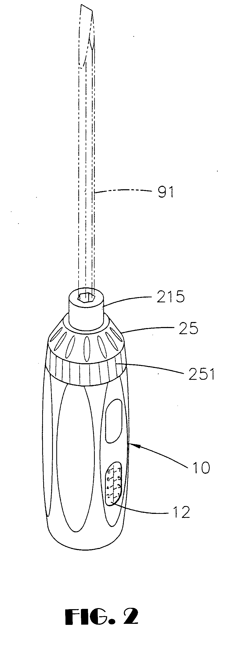
[0022] Referring to FIGS. 1 to 4, a screwdriver in accordance with a first preferred embodiment of the invention comprises a torque setting mechanism 20 and a rotatable handle 10 with most portion of the torque setting mechanism 20 mounted therein. The handle 10 comprises a scale window 12 on its surface. The torque setting mechanism 20 comprises a sleeve 11 including a support ring 111 urged against an upper shoulder by a lower spring (e.g., compression spring) 24 as detailed later, the support ring 111 including a plurality of steel balls 112 equally spaced around its upper surface. The support ring 111 thus is able to turn as the sleeve 11 turns.

[0023] An actuation rod 21 has its most portion disposed in the sleeve 11 by passing the support ring 111 and the spring 24. The actuation rod 21 comprises a lower threaded section 211, an upper threaded section 214, two opposing intermediate flats 213 extended from the upper threaded section 214 to the lower threaded section 211, and a ...


PUM


Abstract

A screwdriver comprises a torque setting mechanism including a torque adjustment ring, an actuation rod threadedly secured to the upper torque adjustment ring and a lower torque adjustment nut, a spring biased sleeve with the actuation rod passed, and a clutch ring snugly put on two opposing intermediate flats of the actuation rod and having an upper surface engaged the torque adjustment ring and a lower surface formed with recesses engaged with steel balls on an upper surface of a support ring in the sleeve. Turning a rotatable handle will turn the sleeve. The clutch ring will disengage with the steel balls if the torque exceeds a set value. Thus, the torque exerted on the handle will not transmit to a shank secured to the actuation rod so as to prevent a screw from being over-driven by the shank.

Description

BACKGROUND OF THE INVENTION [0001] 1. Field of Invention [0002] The present invention relates to screwdrivers and more particularly to a screwdriver having a torque setting mechanism such that torque exerted on a handle will not transmit to a shank if the torque exceeds a set value so as to prevent a screw from being over-driven by the shank. [0003] 2. Related Art [0004] Screwdrivers are well known. It is typical that tightness of a driven screw is determined based on experience of a person working on it. It is understood that in one case the screw may be damaged if force (i.e., torque) exerted thereon exceeds a set value thereof. Thus, it is highly desirable to provide a screwdriver with a torque setting mechanism. However, how to design a torque setting mechanism in a limited internal space of a screwdriver while operation convenience and other advantageous features are still provided is a task to be accomplished. Thus, continuing improvements in the exploitation of such screwdriv...

Claims


Application Information

Patent Timeline
IPC IPC(8): B25B23/14
CPCB25B23/1427B25B15/00
Inventor WANG, CHUN FU
Owner WANG CHUN FU
Learn More