
Method for driving liquid crystal display having multi-channel single-amplifier structure

a liquid crystal display and multi-channel technology, applied in the field of liquid crystal displays, can solve the problems of distortion of video signals and difficult to compensate kick-back nois

Inactive Publication Date: 2007-02-22
SAMSUNG ELECTRONICS CO LTD
View PDF11 Cites 44 Cited by
  • Summary
  • Abstract
  • Description
  • Claims
  • Application Information

AI Technical Summary

Benefits of technology

[0020] The present disclosure provides a liquid crystal driving method for uniformly compensating kick-back noise in a liquid crystal display having a multi-channel single-amplifier structure.

Problems solved by technology

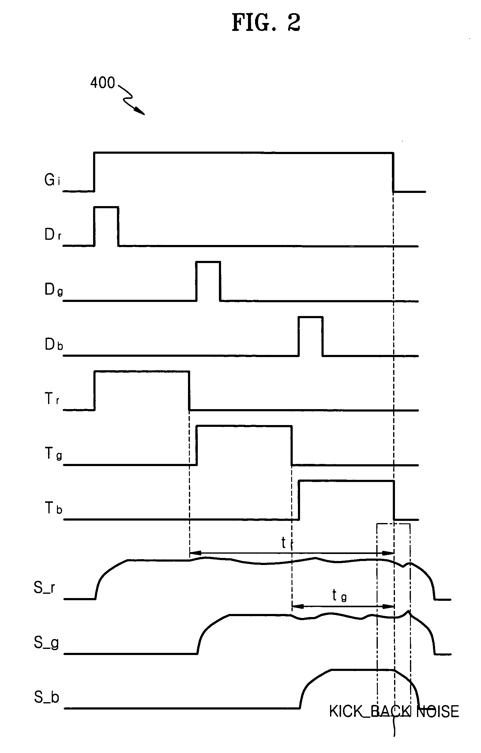
This kick-back noise distorts video signals and varies transmissivity of liquid crystal to cause flicker.
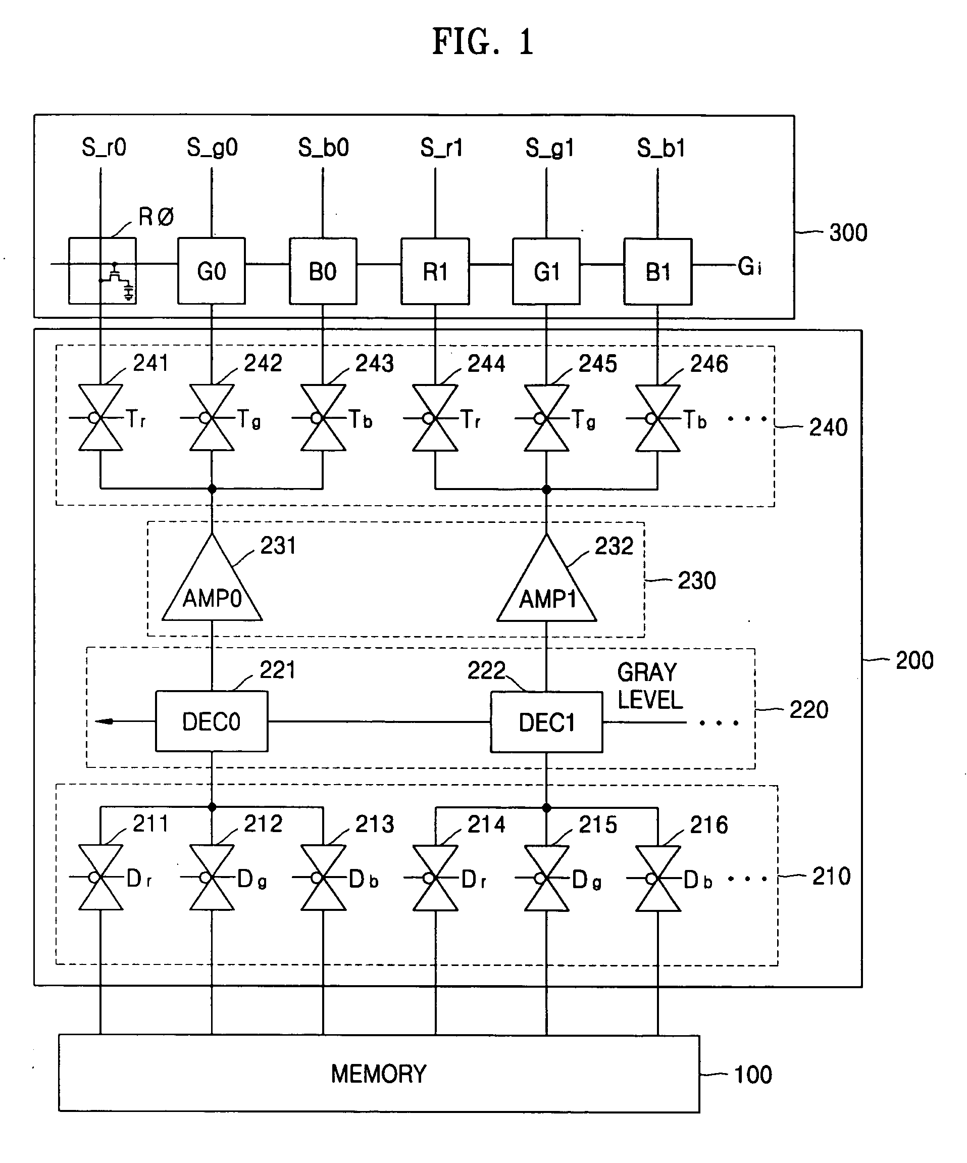
However, it is difficult to compensate the kick-back noise because the source lines S_r0, S_g0, S_b0, S_r1, S_g1 and Sb1 have different kick-back noise components.

Method used


Image

  • Method for driving liquid crystal display having multi-channel single-amplifier structure
  • Method for driving liquid crystal display having multi-channel single-amplifier structure
  • Method for driving liquid crystal display having multi-channel single-amplifier structure

Examples


first embodiment

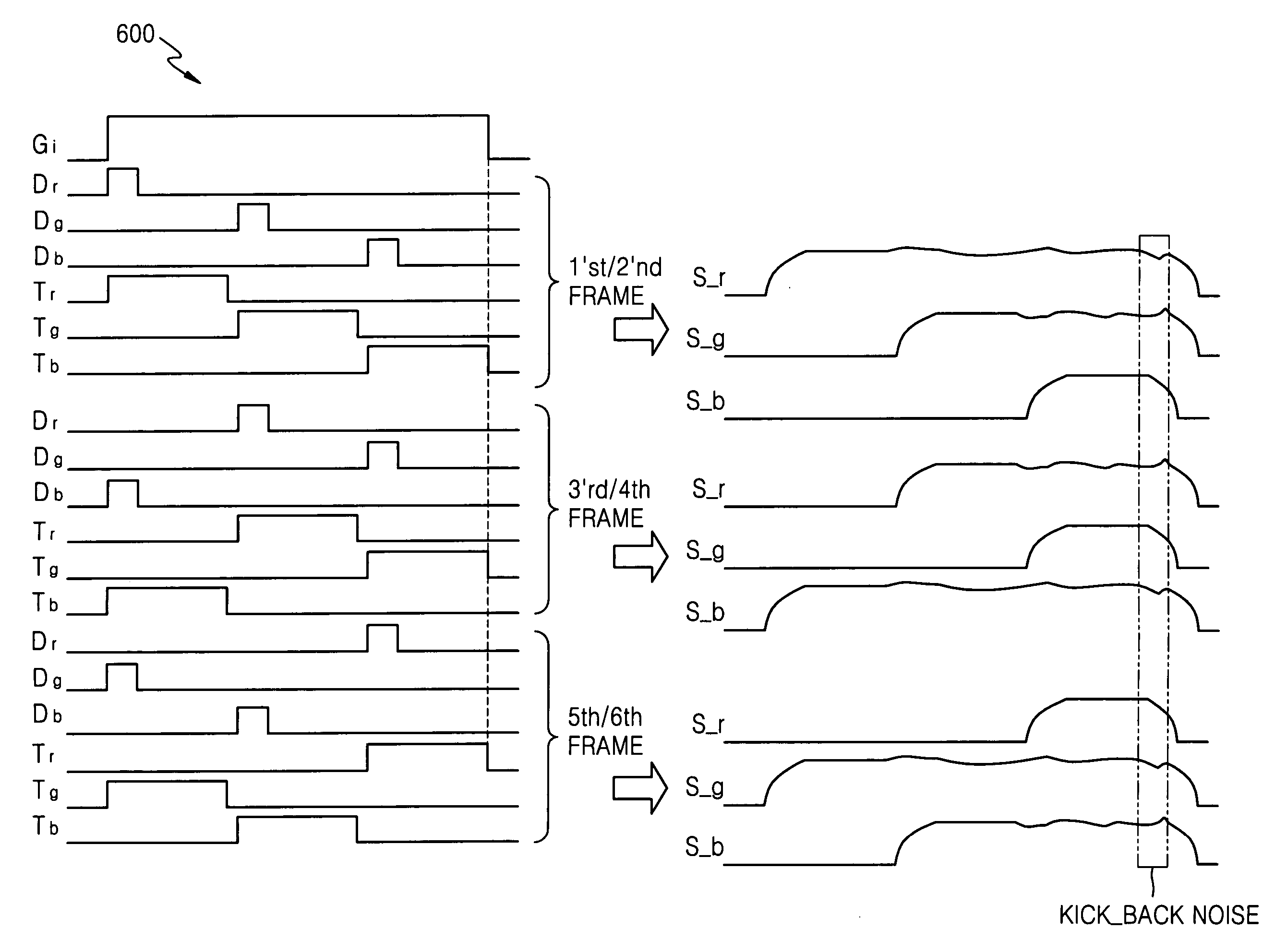
[0037]FIG. 4 is a diagram, indicated generally by the reference numeral 600, for explaining a method of driving a liquid crystal display according to the present disclosure. To prevent pixels from being deteriorated, polarity of each pixel should be inverted for every frame. Thus, the column inversion driving method, in which polarities of liquid crystal along adjacent gate lines are opposite to each other, is applied to embodiments of the present disclosure.

[0038] The method for driving a liquid crystal display according to the present disclosure is explained with reference to FIGS. 1 and 4. Referring to FIG. 4, a method of driving first and second frames is substantially the same as the conventional driving method of FIG. 2. That is, while the gate line Gi is enabled, the signals Dr, Dg and Db are sequentially enabled and then disabled, and signals Tr, Tg and Tb are sequentially enabled. Accordingly, a video signal is applied sequentially to the source lines S_r, S_g and S_b. The ...

second embodiment

[0046]FIG. 5 is a diagram, indicated generally by the reference numeral 700, for explaining a method of driving a liquid crystal display according to the present disclosure. Referring to FIG. 5, in the case of driving the first and second frames, the signals Dr, Dg and Db are sequentially enabled and then disabled, and the signals Tr, Tg and Tb are sequentially enabled while the gate line Gi is enabled. Accordingly, a video signal is applied to the source lines S_r, S_g and S_b, sequentially. The source line S_r is floated when the signal Tr is disabled and the source line S_g is floated when the signal Tg is disabled.

[0047] In the first and second frames, the source line S_r is subjected to coupling twice when the video signal is applied to the source line S_g and the video signal is applied to the source line S_b during the floating period of the source line S_r. The source line S_g is subjected to coupling once when the video signal is applied to the source line S_b.

[0048] In th...


PUM


Abstract

A method is provided for driving a liquid crystal display having a multi-channel single-amplifier structure, where the number of times of coupling according to video signals transmitted to adjacent source lines while the source lines are floated is 3 and it is equal for the respective source lines for 6 frames, noise aspects of the respective source lines are similarly repeated for every 6 frames, kick-back noise compensation is uniformly applied to the source lines S_r, S_g and S_b with noise of the 6 frames averaged, and charge sharing time of parasitic capacitors between the source lines and charge sharing time of capacitors of liquid crystal cells become similar to each other.

Description

CROSS-REFERENCE TO RELATED APPLICATION [0001] This application claims foreign priority under 35 U.S.C. §119 to Korean Patent Application No. 10-2005-0074913, filed on Aug. 16, 2005, in the Korean Intellectual Property Office, the disclosure of which is incorporated by reference herein in its entirety. BACKGROUND OF THE INVENTION [0002] 1. Field of the Invention [0003] The present disclosure relates to liquid crystal displays, and more particularly relates to methods for driving liquid crystal displays having multi-channel single-amplifier structures. [0004] 2. Description of the Related Art [0005] A liquid crystal display displays images corresponding to video signals using a pixel matrix arranged between gate lines and source lines. Each pixel includes a liquid crystal cell that controls light transmissivity in response to a video signal, and a thin film transistor that transfers a video signal from a source line to the liquid crystal cell. The liquid crystal display includes a gat...

Claims


Application Information

Patent Timeline
Patent Type & Authority Applications(United States)
IPC IPC(8): G09G3/36
CPCG09G3/3607G09G3/3688G09G2310/0291G09G2310/08G09G2320/0219G09G2320/0247G09G3/20G09G3/36
Inventor WOO, JAE-HYUCKCHOI, JONG-HAN
Owner SAMSUNG ELECTRONICS CO LTD
Learn More