Electrical Hand Power Tool with Battery Pack

a technology of hand power tools and battery packs, which is applied in the direction of portable power tools, manufacturing tools, cell components, etc., can solve the problems of failure of locking action and greater play

Inactive Publication Date: 2008-05-01
ROBERT BOSCH GMBH
View PDF26 Cites 24 Cited by
  • Summary
  • Abstract
  • Description
  • Claims
  • Application Information

AI Technical Summary

Problems solved by technology

As a consequence of this play, because of operation-caused vibration and the inertia of the battery pack, relative motion between the battery pack and the housing of the hand power tool occurs in operation of the hand po...

Method used


Image

  • Electrical Hand Power Tool with Battery Pack
  • Electrical Hand Power Tool with Battery Pack
  • Electrical Hand Power Tool with Battery Pack

Examples


Embodiment Construction

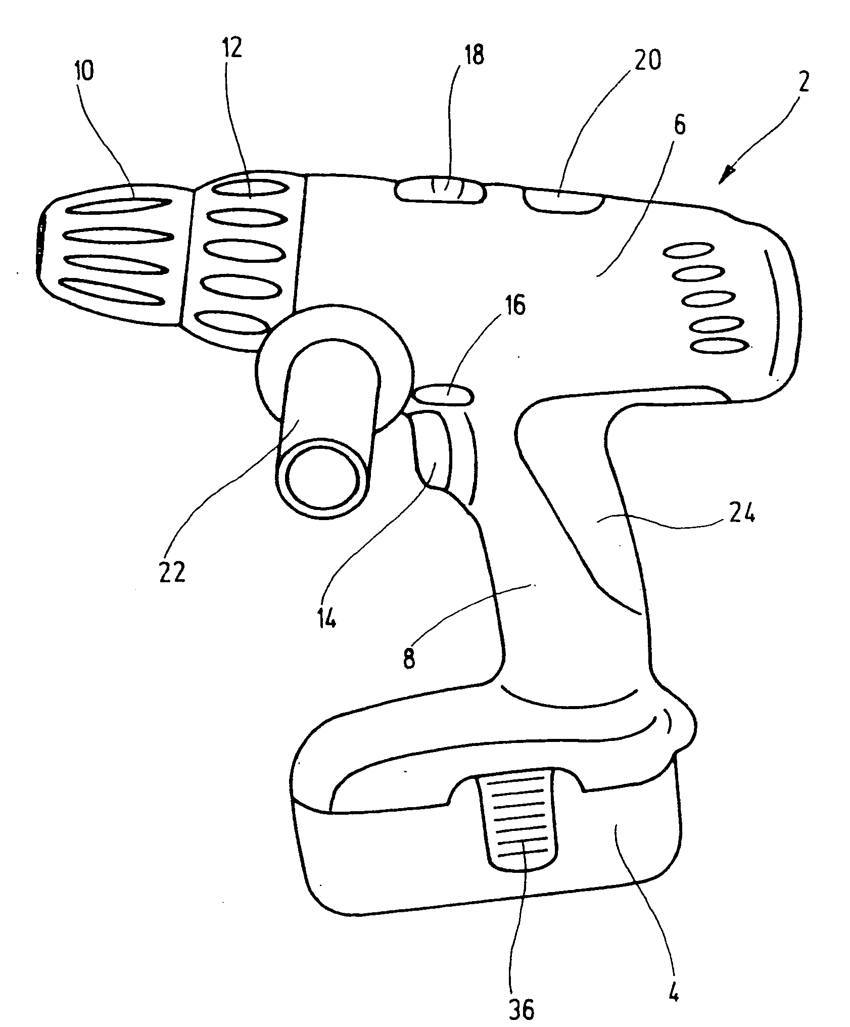
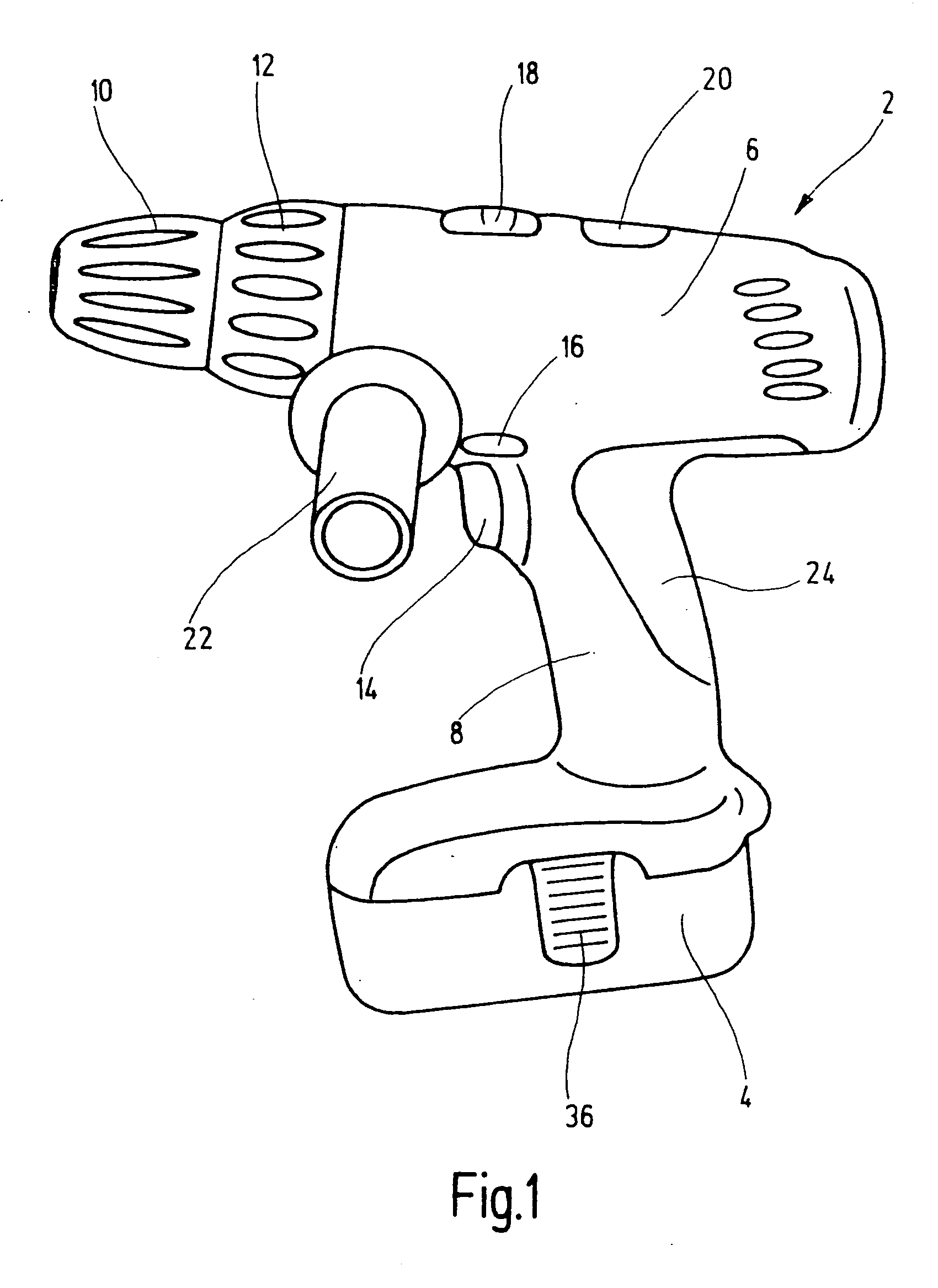
[0014]The electrical percussion drill screwdriver 2 with a battery pack 4 shown in the drawing essentially comprises a housing 6 with a grip part 8, an electric motor with a step-down gear (not shown), accommodated in the housing 6, a quick-action drill chuck 10, protruding past the housing 6 and driven by the step-down gear, for chucking a drill or screw insert (not shown), a torque adjusting ring 12 located between the fast-action drill chuck 10 and the housing 6, and the battery pack 4, locked releasably to the lower end of the grip part, for supplying direct current to the electric motor independently of the power grid.

[0015]The housing 6 of the percussion drill screwdriver 2 is provided, on the upper end of the grip part 8, with an on / off switch 14 and a rotation or direction-reversing switch 16 with an activation lock and on its top, it has a switch 18 for first and second gear and also has a magnet plate 20. An additional handle 22 is releasably secured to one side of the hou...


PUM


Abstract

The invention relates to a hand power tool (2), having a housing (6), an electric motor accommodated in the housing (6), and a battery pack (4), releasably locked to the housing (6), for supplying the electric motor with electric current. At least one spring/damping element (38), mounted between the battery pack (4) and the housing (6) of the hand power tool (2), is provided, for damping vibration and -or eliminating a locking-dictated play between the battery pack (4) and the housing (6).

Description

[0001]The invention relates to an electrical hand power tool, having a housing, a direct-current motor accommodated in the housing, and a battery pack, which can be locked to the housing, for supplying the direct-current motor with electric current.PRIOR ART [0002]Electrical hand power tools, such as percussion screwdrivers, power drills, right angle grinders, saber saws, circular saws, or planing machines for professional craftsmen or the do-it-yourselfer typically have either an alternating current motor or a direct-current motor as the driving motor. While the alternating current motor is as a rule supplied with alternating current from the power grid via a power cord, the electrical energy for supplying the direct-current motor is as a rule provided by a so-called battery pack, that is, a rechargeable battery in a housing that can be coupled to the housing of the hand power tool and that is connected electrically to the power supply lines of the direct-current motor when the two...

Claims


Application Information

Patent Timeline
IPC IPC(8): B25F5/00H01M2/10H01M50/242H01M50/244H01M50/247
CPCH01M2/1022B25F5/006Y02E60/10H01M50/247H01M50/242H01M50/244
Inventor HOFMANN, ALBRECHTKRONDORFER, HARALDHECKMANN, MARKUSHECKMANN, KERSTENSCHADOW, JOACHIMSCHOMISCH, THOMAS
Owner ROBERT BOSCH GMBH
Why Eureka
Try Eureka