Display device and electric apparatus using the same
a technology of electric apparatus and display device, which is applied in the direction of optics, instruments, optical elements, etc., can solve the problems of difficult to reduce the voltage applied to move the liquid, the drive voltage of the display device, and the insufficient study of conductive liquid, etc., to achieve excellent display performance, low power consumption, and excellent operation performance.
- Summary
- Abstract
- Description
- Claims
- Application Information
AI Technical Summary
Benefits of technology
Problems solved by technology
Method used
Image
Examples
embodiment 1
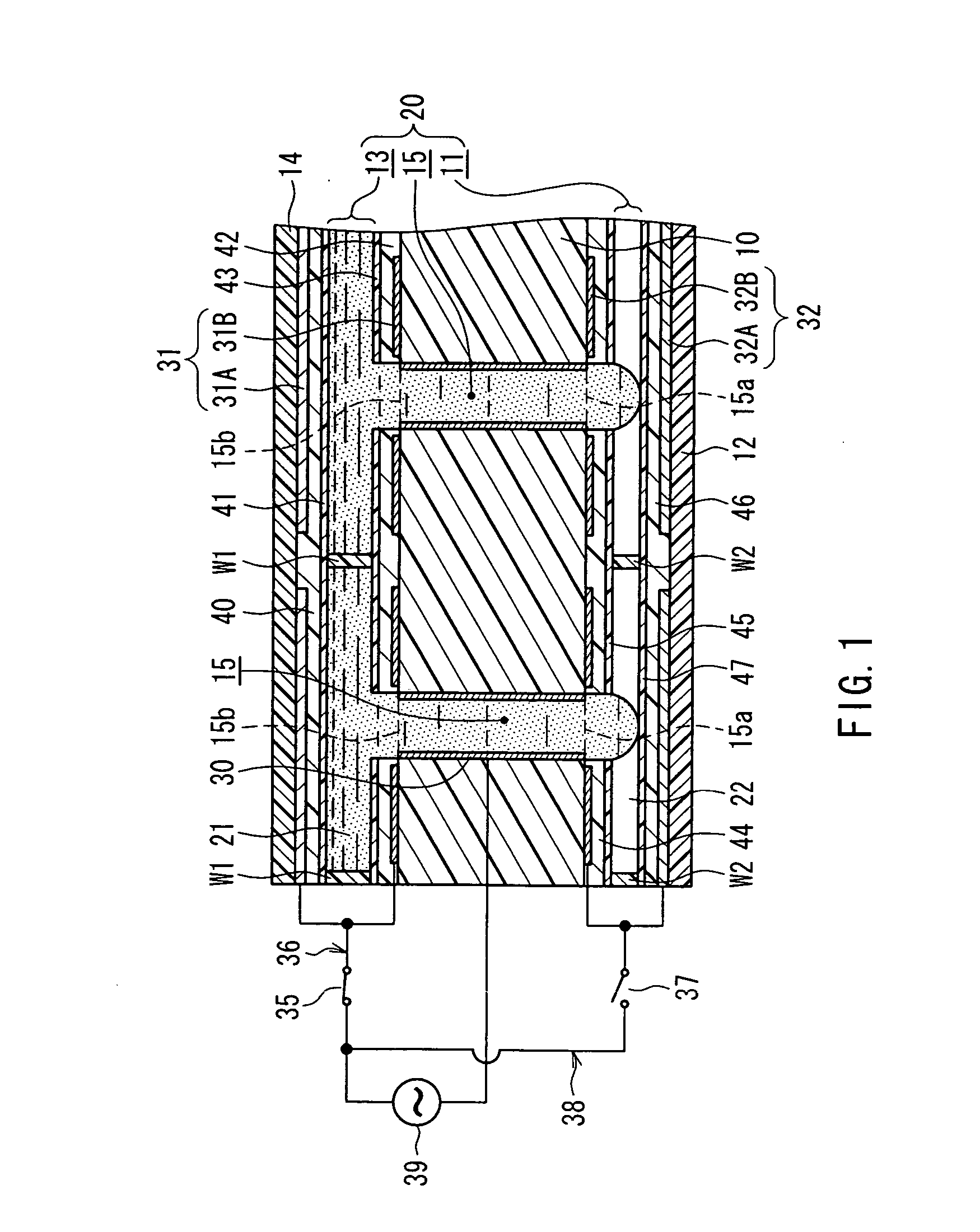
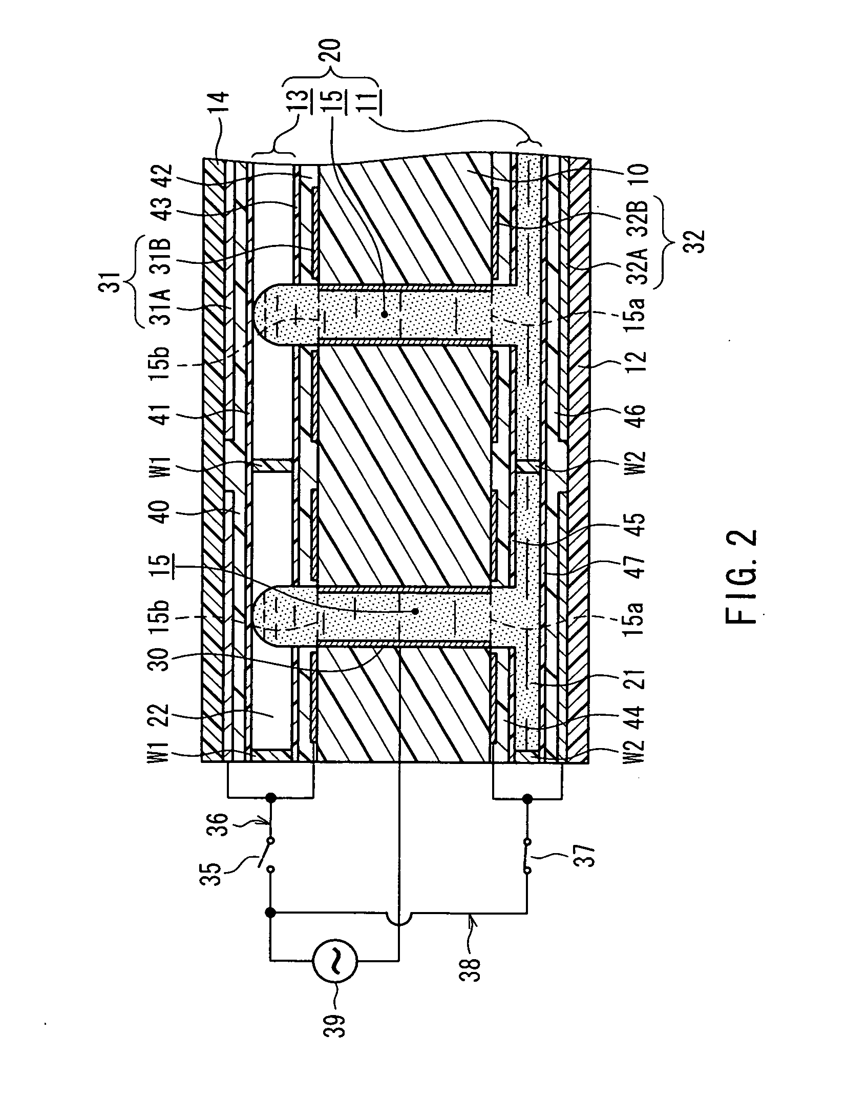
[0065]FIG. 1 is a sectional view showing a configuration of a main portion of a display device and an image display according to Embodiment 1 of the present invention in a state of displaying a color resulting from a liquid. FIG. 2 is a sectional view showing the configuration of the main portion of the display device and the image display described above in a state of displaying white.
[0066] In FIGS. 1 and 2, the image display according to the present embodiment is provided with a display portion constituted by the display device according to the present invention. In this display portion, an upper side in the figure corresponds to a display surface side recognized visually by a user. The above-noted display device includes a light-scattering sheet 10 for scattering external light from the display surface side so as to display white, a lower electrode substrate 12 provided on a non-display surface side of the light-scattering sheet 10 such that a rectangular lower space 11 is form...
first modified embodiment
[0132]FIG. 3A is a sectional view showing a configuration of a main portion of a first modified embodiment of the display device and the image display shown in FIG. 1 in the state of displaying a color resulting from the liquid. FIG. 3B is a sectional view showing the configuration of the main portion of the display device and the image display shown in FIG. 3A in the state of displaying white. In these figures, a main difference between the present modified embodiment and Embodiment 1 described above lies in the use of a conductive metal thin film as the common electrode. Incidentally, elements provided in common with Embodiment 1 described above are given the same reference numerals, and the redundant description thereof will be omitted here.
[0133] As shown in FIGS. 3A and 3B, in the present modified embodiment, a thinner light-scattering sheet 10 is used, and a common electrode sheet 50 and an insulating sheet 51 are layered in this order on this light-scattering sheet 10 on the...
second modified embodiment
[0136]FIG. 4 is a sectional view showing a configuration of a main portion of a second modified embodiment of the display device and the image display shown in FIG. 1 in the state of displaying a color resulting from the liquid. In this figure, a main difference between the present modified embodiment and the first modified embodiment described above lies in the use of the air instead of the nonpolar oil. Incidentally, elements provided in common with the first modified embodiment described above are given the same reference numerals, and the redundant description thereof will be omitted here.
[0137] In FIG. 4, in the present modified embodiment, a transparent air A is sealed so as to be movable in the liquid storage portion 20. This air A has a physical property of not mixing with the conductive liquid 21 and moves inside the liquid storage portion 20 according to the movement of the conductive liquid 21 similarly to the nonpolar oil 22 described above. More specifically, when the ...
PUM
 Abstract
Description
Claims
Application Information
 - R&D
- Intellectual Property
- Life Sciences
- Materials
- Tech Scout
- Unparalleled Data Quality
- Higher Quality Content
- 60% Fewer Hallucinations
Browse by: Latest US Patents, China's latest patents, Technical Efficacy Thesaurus, Application Domain, Technology Topic, Popular Technical Reports.
© 2025 PatSnap. All rights reserved.Legal|Privacy policy|Modern Slavery Act Transparency Statement|Sitemap|About US| Contact US: help@patsnap.com


