
Suturing device and method

a suction device and suction tube technology, applied in the field of suction devices, can solve the problems of thrombosis patch rupture or burst, patient bleeding to death, and needing to apply pressure, and achieve the effect of reducing many complications and costs

Inactive Publication Date: 2007-02-22
SCARAB TECH SERVICES LLC +2
View PDF87 Cites 78 Cited by
  • Summary
  • Abstract
  • Description
  • Claims
  • Application Information

AI Technical Summary

Benefits of technology

This approach enables efficient closure of blood vessel openings without prolonged pressure application, reducing complications and hospital stays, and minimizes patient discomfort and medical expenses by facilitating suturing in a minimally invasive manner.

Problems solved by technology

A significant problem with this approach is that it is frequently necessary to apply the pressure for an extended period of time, such as twenty-four hours or longer.
Another problem with the thrombus patch method is that the high blood pressure in the artery can cause the thrombus patch to rupture or burst while direct pressure is being applied to the thigh or after direct pressure is removed.
If the patch ruptures and is not restored, the patient may bleed to death.
Because thrombus patches frequently burst, the patient frequently must remain in the hospital or catheterization lab overnight for observation.
Thus, these ‘out-patient’ procedures become ‘in-patient’ procedures, simply because a thrombus patch it is difficult to create.
Staying in the hospital increases patient discomfort and hospital expenses, which are often disproportionate to the actual medical procedure performed.
Furthermore, if a thrombus patch cannot be formed, the physician may need to anesthetize the patient, occlude blood flow to the artery, make a large incision in the thigh to allow conventional suturing with a needle, suture the artery with conventional means, restore blood flow to the artery, and suture the incision in the thigh.
This results in additional discomfort and expenses for the patient.
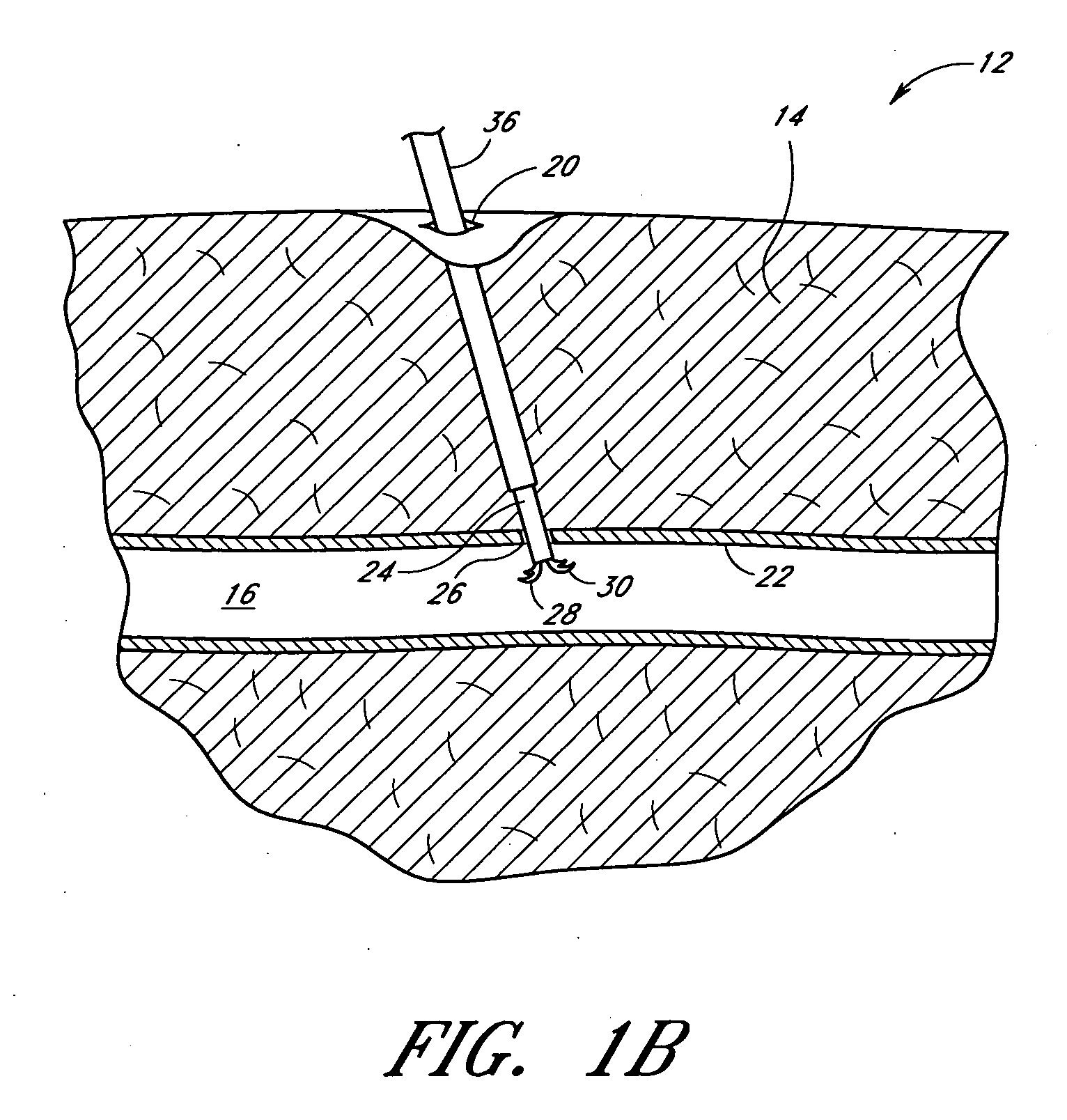
While the above problems could potentially be avoided by suturing the blood vessel immediately following the catheterization procedure, the size and location of the artery make suturing difficult.
Specifically, the opening in the thigh is typically too small and too deep to provide enough working space for suturing the artery using conventional methods.
Thus, in order to suture the vessel according to conventional methods, the opening in the thigh would have to be significantly enlarged, potentially exposing the patient to additional pain, scarring, and health risks.

Method used


Image

  • Suturing device and method
  • Suturing device and method
  • Suturing device and method

Examples


embodiments

Six-Arm and Eight-Arm Embodiments

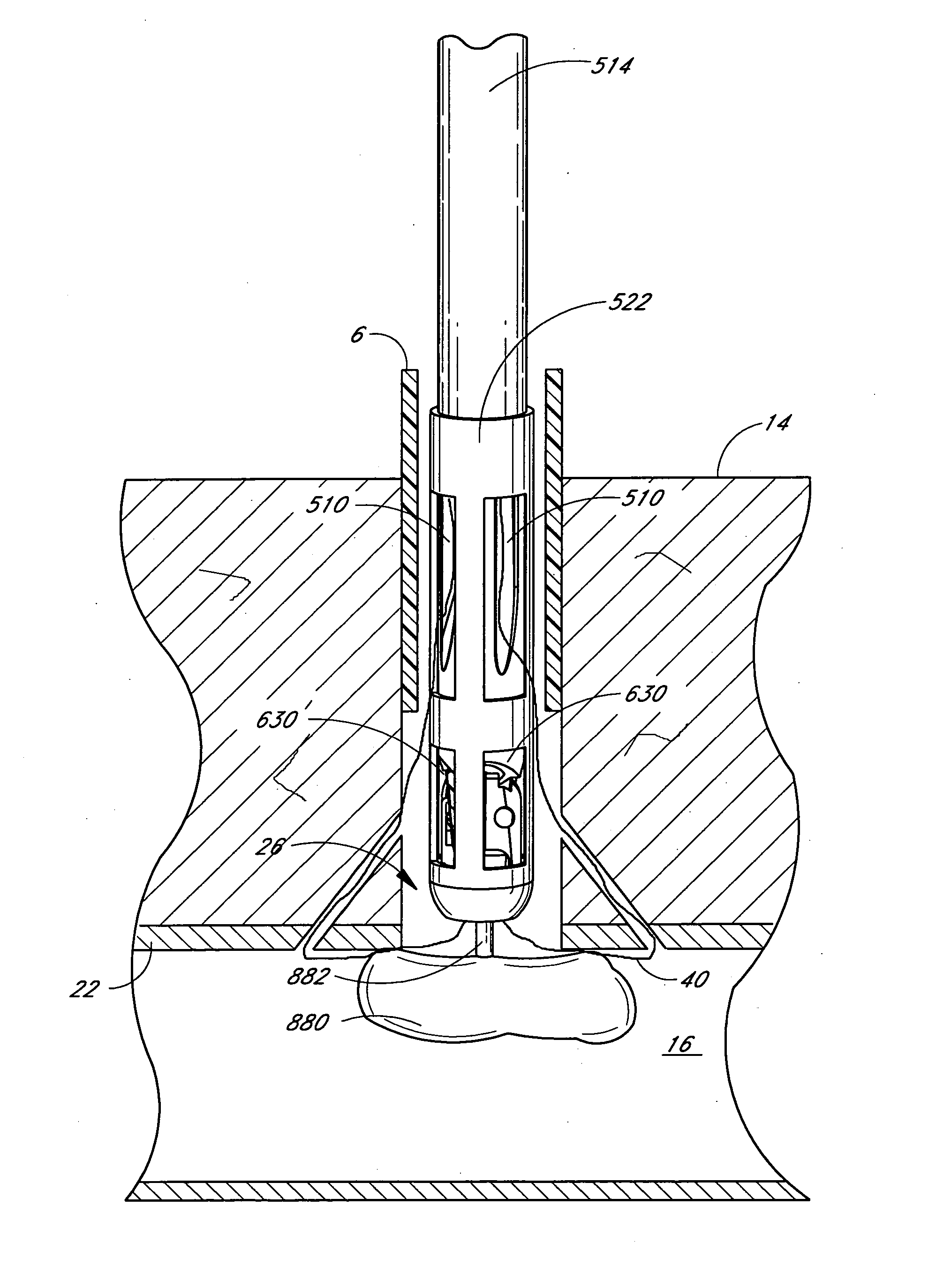
[0267]FIGS. 62-65 illustrate another suture device configuration 750. FIG. 62 is a perspective view of the suture device 750 with six suture clasp arms 756-766 (only three of which are visible in FIG. 62). FIG. 63 is a perspective view of the device 750 of FIG. 62 with the suture clasp arms 756-766 fully deployed. FIG. 64 is a perspective view from the distal end of the device 750 of the six suture clasp arms 756-766 of FIG. 62. FIG. 65 is a perspective view of the device of FIG. 62 with the suture clasp arms fully deployed and a set of needles engaging the suture clasp arms.

[0268] In FIG. 62, the structure of the suture introducer head 752 is substantially similar to the suture introducer head 522 of FIG. 52A, except the suture introducer head 752 in FIG. 62 comprises six suture arm apertures 508 and six needle apertures 510. Similarly, the structure of the hollow elongated body 754 in FIG. 62 is substantially similar to the structure of the hollow...

embodiment

Alternate Handle Embodiment

[0309]FIG. 74A is a perspective view of another embodiment of a handle 900 capable of being attached to the proximal end of the device of FIG. 41, the device of FIG. 48 or the device of FIG. 52A. Similarly, FIG. 74B is a perspective view of another embodiment of a handle 900 adapted to separately actuate the first and second needles. A portion of the main housing 910 has been removed in FIGS. 74A and 74B to expose the interior. FIGS. 75A and 75B are exploded, perspective views of the embodiment shown in FIG. 74A. FIG. 76A is an exploded, perspective view of the embodiment shown in FIG. 74B, and FIGS. 76B-D schematically illustrate various embodiments of the needle drivers adapted to separately actuate the first and second needles. FIGS. 74B and 76A-D will be described more fully below in connection with the non-simultaneous actuation of the first and second needles.

[0310] In FIGS. 74A, 75A, and 75B, the handle 900 comprises a thumb ring 902, a plunger 904...


PUM


Abstract

A suturing device and method allows a physician to remotely suture biological tissue. The device includes an elongate body, first and second arms operably connected to the elongated body, whereby each arm mounts an end portion of a suture, and first and second needles, each needle having a distal end and being mounted such that the distal end of the needle is movable to engage respective end portions of said suture. The suturing apparatus further includes an actuator which drives the needles to engage the suture. The suturing apparatus further includes an occluding device operably connected to the elongate body such that the occluding device may be advanced from the distal end of the elongate body to temporarily occlude the incision to be sutured.

Description

RELATED APPLICATIONS [0001] This application is a continuation of U.S. Utility patent application Ser. No. 10 / 435,928, filed May 12, 2003, which is a continuation of U.S. Utility patent application Ser. No. 09 / 881,550, filed Jun. 14, 2001, which is a continuation-in-part of International Patent Application No. PCT / US01 / 08050, filed Mar. 13, 2001 and published in English on Sep. 20, 2001 as PCT Publication WO 01 / 67963, and a continuation-in-part of U.S. Utility patent application Ser. No. 09 / 524,211, filed Mar. 13, 2000, which is a continuation-in-part of U.S. Utility patent application Ser. No. 09 / 471,866, filed Dec. 23, 1999, which is a continuation of U.S. Utility patent application Ser. No. 09 / 231,177, filed Jan. 14, 1999, now U.S. Pat. No. 6,117,144, which is a continuation-in-part of U.S. Utility patent application Ser. No. 09 / 036,437, filed Mar. 9, 1998, which is a continuation-in-part of U.S. Utility patent application Ser. No. 08 / 702,315, filed Aug. 23, 1996, now U.S. Pat. N...

Claims


Application Information

Patent Timeline
Patent Type & Authority Applications(United States)
IPC IPC(8): A61B17/04A61B17/00A61B17/28
CPCA61B17/0057A61B17/0469A61B17/0482A61B17/0491A61B17/06166A61B17/0625A61B2017/2911A61B2017/00659A61B2017/00663A61B2017/00672A61B2017/00867A61B2017/0472A61B2017/06042A61B2017/00637
Inventor NOBLES, ANTHONY A.DECKER, STEVEN E.BROSCH, BENJAMIN G.
Owner SCARAB TECH SERVICES LLC
Learn More