

Reverse tapered guidewire and method of use
- Summary
- Abstract
- Description
- Claims
- Application Information
AI Technical Summary
Benefits of technology
Problems solved by technology
Method used
Image

Examples
Embodiment Construction
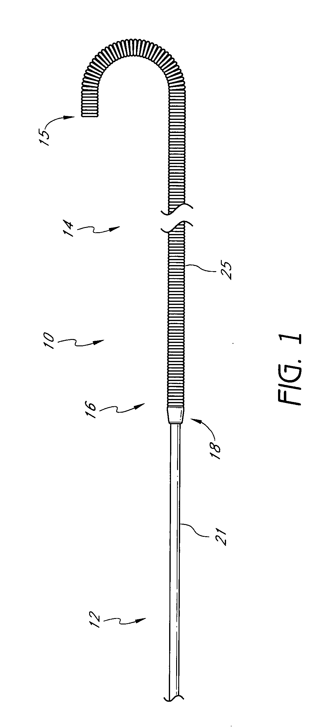
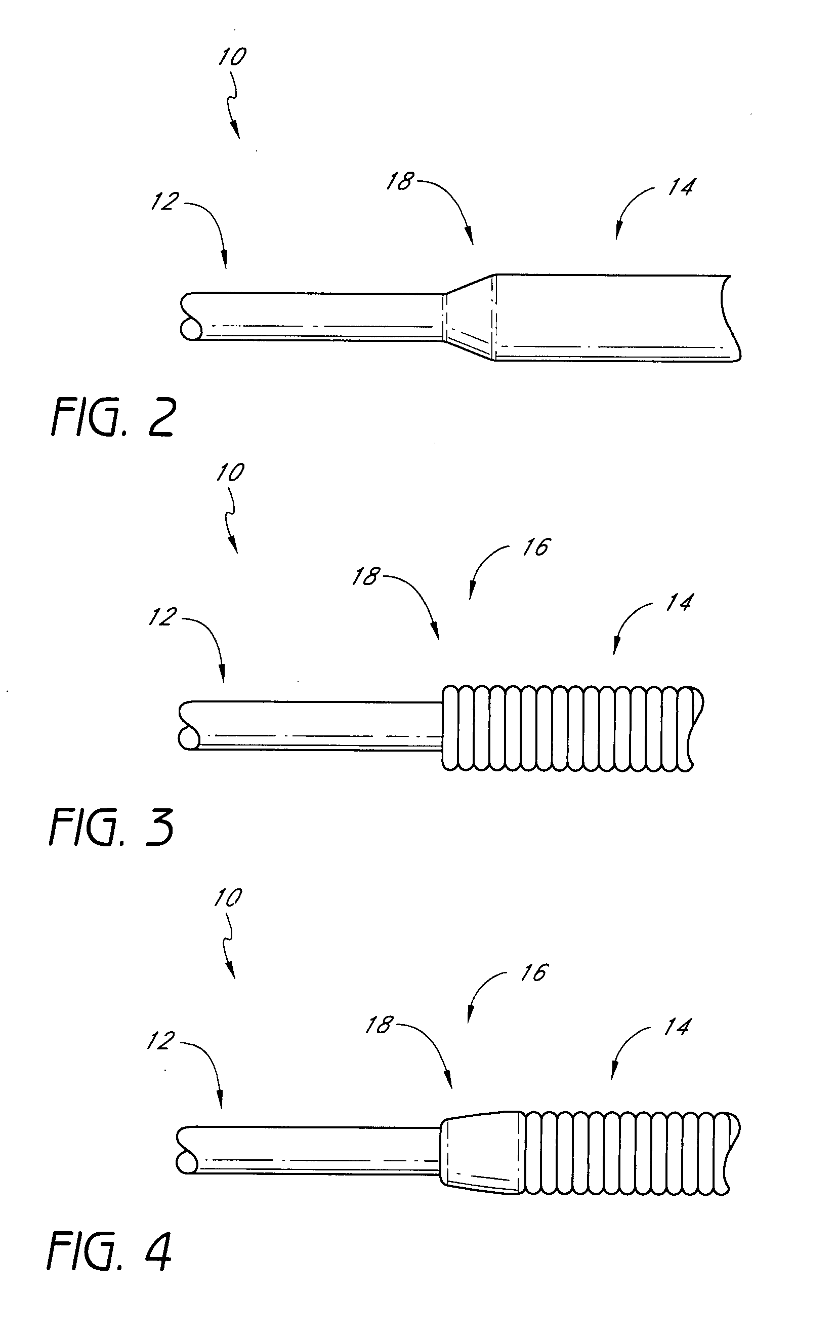
[0051]FIG. 1 illustrates an embodiment of a reverse tapered guidewire 10, having a distal segment 14 and a proximal segment 12. As used herein, the term “reverse tapered” refers to the guidewire being smaller in the proximal segment 12 than in the distal segment 14 The guidewire 10 need not necessarily have a gradual transition 18 from the distal segment 14 to the proximal segment 12. Thus, in one embodiment, illustrated in FIG. 3, the guidewire 10 may have a distinct step between the proximal segment 12 and distal segment 14, but have a constant or substantially constant cross-section between the proximal end and the transition 18 between the proximal and distal segments. In other embodiments, a gradual taper may be provided, as shown in FIGS. 2 and 4.
[0052] In one embodiment, the length of the guidewire 10 ranges from about 50 cm to about 320 cm, more typically ranging from about 120 cm to about 200 cm, and preferably from about 175 cm to about 190 cm for the coronary anatomy or ...
PUM
 Abstract
Description
Claims
Application Information