Radial and trans-endocardial delivery catheter

a technology of endocardial catheter and radial endocardium, which is applied in the field of medical methods and systems to achieve the effect of sufficient column strength and pushability

Active Publication Date: 2018-09-11
BIOCARDIA
View PDF38 Cites 2 Cited by
  • Summary
  • Abstract
  • Description
  • Claims
  • Application Information

AI Technical Summary

Benefits of technology

[0018]In a first aspect, the present invention provides methods for introducing needle injection catheters into a heart chamber via a radial artery approach. Such methods comprise advancing a guide catheter through the radial artery (and the intervening arterial vasculature) and into a targeted heart chamber. The catheter will usually enter the right or left ventricle from the right side of the heart but may be further advanced transeptally within the heart to reach the left ventricle from the right side of the heart or other chambers. The guide catheter is positioned to align a distal tip of the guide catheter with a target location on an endocardial wall of the heart chamber. A needle-injection catheter is advanced through a lumen of the guide catheter so that a straight needle projecting coaxially from a distal tip of the needle injection catheter emerges from the distal tip and penetrates the endocardial wall to position an injection port at the tip of the needle in the myocardium. A plurality of penetration limiting elements remain constrained within the guide catheter until the straight needle emerges from the distal tip at which point the elements self-deploy radially outwardly from a base of the needle, typically resiliently deploying as a result of their own spring-force upon the release of constraint, to limit the penetration of the needle into the myocardium in order to reduce the risk of perforation of the endocardial wall.
[0022]In a second aspect, the present invention provides a needle-injection catheter comprising a catheter body having a distal end, a proximal end, a stiff proximal portion, a flexible distal portion, and a delivery lumen extending therethrough. By stiff, it is meant that the proximal portion of the catheter body will have sufficient column strength and pushability to be advanced through relatively non-tortuous regions of the vasculature and in particular from the radial artery to the heart. By flexible, it is meant that the distal portion will be able to be advanced across small radius curves to allow positioning within the heart chamber and through pre-shaped or deflected regions of the guide catheter. The catheter further includes a straight injection needle extending coaxially from a distal tip of the flexible portion of the catheter body. A plurality of penetration limiting elements are positioned circumferentially about a base of the straight injection needle and are configured to fold radially inwardly against a shaft of the needle when constrained in a tubular lumen and to extend radially outwardly when unconstrained.
[0025]In further embodiments of the present invention, a catheter system comprises a needle-injection catheter as described above in combination with a guide catheter having a lumen configured to receive the needle-injection catheter and to radially constrain the plurality of penetration limiting elements when the needle-injection catheter is therein. The guide catheter of such a system may have a pre-shaped bend near its distal end so that the guide catheter can be rotated to align the distal end with a target location on an endocardial wall when the guide catheter is in a heart chamber. Alternatively, the guide catheter may have a deflectable (also referred to as steerable) distal end to allow aligning the distal end with a target location on an endocardial wall when the guide catheter is in a heart chamber.

Problems solved by technology

These systems are passive systems but consume real estate in the distal end of the catheter and require a distal catheter shaft construction that would prevent transradial access because of size.

Method used


Image

  • Radial and trans-endocardial delivery catheter
  • Radial and trans-endocardial delivery catheter
  • Radial and trans-endocardial delivery catheter

Examples


Embodiment Construction

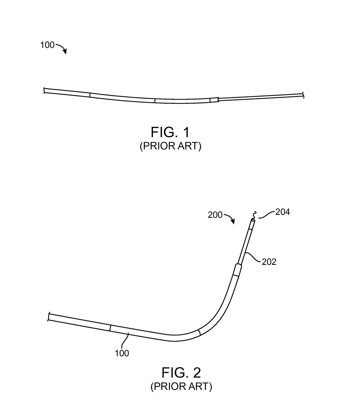
[0050]FIG. 1 (Prior Art) shows a preformed 6F Hockey Stick (HS) 90 cm guide catheter 100, such as the ConcierGE® Guiding Catheter, available from Merit Medical Systems, Inc., which is advanced straight or over either a dilator or a guide wire from either the femoral or radial artery. Because the distal segment is highly flexible, the guide catheter may be safely advanced across the aortic valve into the left ventricle. The guide catheter 100 may be advanced into a femoral artery using any commercially available 6 Fr sheath. For radial access, a longer 25 cm sheath such as the Boston Scientific Super Sheath Catalog 16037-06B is preferred to avoid complications with radial artery spasm which occurs frequently in patients.

[0051]FIG. 2 (Prior Art) shows the preformed 6 Fr HS 90 cm guide catheter 100 after a central straightening element, such as a dilator or wire, is removed and a trans-endocardial infusion catheter 200 with a highly flexible distal segment 202 with a length of at least...


PUM


Abstract

A needle-injection catheter includes a catheter body having a distal end, a proximal end, a stiff proximal portion, a flexible distal portion, and a delivery lumen extending therethrough. In a first embodiment, a straight injection needle extends coaxially from a distal tip of the flexible portion of the catheter body, and a plurality of penetration limiting elements positioned circumferentially about a base of the straight injection needle and configured to fold radially inwardly against a shaft of the needle when constrained in a tubular lumen and to extend radially outwardly when unconstrained. In a second embodiment, a helical needle extends from the distal tip of the flexible portion of the catheter body. The helical needle has at least one helical delivery lumen connected to receive an injectable substance from the delivery lumen of the catheter body.

Description

CROSS-REFERENCE TO RELATED APPLICATIONS[0001]This application claims the benefit of U.S. Provisional Application No. 61 / 884,834, filed Sep. 30, 2013, the entire content of which is incorporated herein by reference.BACKGROUND OF THE INVENTION[0002]1. Field of the Invention[0003]The present invention relates generally to medical methods and systems. More particularly, the present invention relates to medical methods and systems suitable for substance delivery to the heart via a radial artery and for the intracardiac delivery of cellular aggregates and other agglomerated materials.[0004]Currently, local biotherapeutic delivery to the heart is under clinical investigation for the treatment of acute myocardial infarction, chronic myocardial ischemia, ischemic heart failure, and nonischemic heart failure. The leading paradigm of intramyocardial delivery is trans-endocardial delivery.[0005]Currently available delivery systems include the Myostar® catheter, manufactured by Johnson and Johns...

Claims


Application Information

Patent Timeline
Patent Type & Authority Patents(United States)
IPC IPC(8): A61M25/06A61M25/09
CPCA61M25/0606A61M25/09A61M2025/09166A61M2025/09175A61M2025/09191A61M25/0084A61M2025/0089A61B2017/00247A61B2090/036
Inventor HSUEH, WAIPALMER, OLIN JAYCOMISO, SCOTTROSS, JAMES B.VIEN, KENARGENTIERI, JULIOALTMAN, PETER
Owner BIOCARDIA
Why Eureka
Try Eureka