
Capture, analysis, and visualization of concurrent system and network behavior of an application

a technology of concurrent system and network behavior, applied in the field of computer applications, can solve the problems of not providing any insight as to the activities of the application, difficult to distinguish events from one application from among events of other applications, and increasing popularity of the distributed application

Active Publication Date: 2007-02-22
RIVERBED TECH LLC
View PDF16 Cites 159 Cited by
  • Summary
  • Abstract
  • Description
  • Claims
  • Application Information

AI Technical Summary

Benefits of technology

[0008] It is an objective of this invention to provide a method and system for capturing application-related events across a network, as well as within nodes / processors of the network. It is a further object of this invention to provide a method and system for analyzing captured network and processor / system events and to produce an integrated view of the delays incurred as application-related messages are communicated and processed among the distributed nodes / processors of a network.

Problems solved by technology

With advances in networking technology, distributed applications continue to grow in popularity, and in complexity.
This task, if feasible, is complicated by the fact that the application is generally run in an operational environment, and distinguishing events from one application from among events of other applications is often difficult.
These visualizations of the data communications illustrate the time spent at each node, but do not provide any insight as to the activities that consume the time at each node.
This conventional segregation of analysis tasks, between network analysis and system analysis, is poorly suited for analyzing the performance of distributed applications that increasingly rely upon a proper balance of network and system capabilities and interactions.

Method used


Image

  • Capture, analysis, and visualization of concurrent system and network behavior of an application
  • Capture, analysis, and visualization of concurrent system and network behavior of an application
  • Capture, analysis, and visualization of concurrent system and network behavior of an application

Examples


Embodiment Construction

[0019] In the following description, for purposes of explanation rather than limitation, specific details are set forth such as the particular architecture, interfaces, techniques, etc., in order to provide a thorough understanding of the concepts of the invention. However, it will be apparent to those skilled in the art that the present invention may be practiced in other embodiments, which depart from these specific details. In like manner, the text of this description is directed to the example embodiments as illustrated in the Figures, and is not intended to limit the claimed invention beyond the limits expressly included in the claims. For purposes of simplicity and clarity, detailed descriptions of well-known devices, circuits, and methods are omitted so as not to obscure the description of the present invention with unnecessary detail.

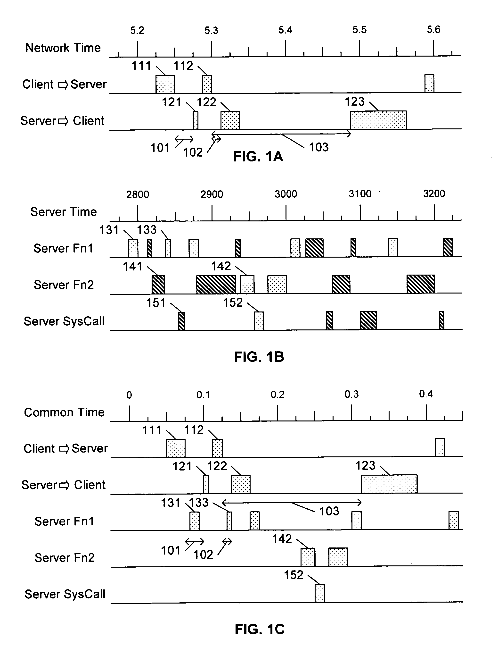
[0020]FIG. 1A illustrates an example timing diagram corresponding to messages communicated on a network between a client and a server during e...


PUM


Abstract

A first capture system that captures network communication events related to an application, and a second capture system that captures internal processing events related to the application. A visualization system analyzes the data captured by each of the capture systems, synchronizes and correlates the data, and presents an integrated display of these communication and processing events. In a preferred embodiment, the communicated messages include an identifier of the application, and the processing components also associate an identifier of the application to each recorded processing event. To facilitate the integrated display of the events, the visualization system synchronizes the recorded communication and processing events to a common time base.

Description

[0001] This application claims the benefit of U.S. Provisional Patent Application 60 / 709,762 filed 19 Aug. 2005.BACKGROUND AND SUMMARY OF THE INVENTION [0002] This invention relates to the field of computer applications, and in particular to distributed applications that include communications among processors on a network. [0003] With advances in networking technology, distributed applications continue to grow in popularity, and in complexity. In a typical distributed application, a client device may initiate the application, and the application may execute a request for data services at a remote server, and this remote server may in turn request data or other processing from other remote servers. The executed processes at the servers may be specific components of the application residing at the servers, or they may be components provided by the servers and accessed by the application. [0004] Users of an application are generally sensitive to performance and reliability issues asso...

Claims


Application Information

Patent Timeline
Patent Type & Authority Applications(United States)
IPC IPC(8): G06F15/173
CPCH04L41/046H04L41/0631H04L67/10H04L67/36H04L41/22H04L67/75
Inventor BARON, STEVEN J.MALLOY, PATRICK J.COHEN, ALAIN J.SCHNEIDER, MARC I.STOCKS, CHERYL D.
Owner RIVERBED TECH LLC
Learn More