Blouse front closer

Inactive Publication Date: 2007-03-01
WHICKER REBECCA
View PDF28 Cites 12 Cited by
  • Summary
  • Abstract
  • Description
  • Claims
  • Application Information

AI Technical Summary

Benefits of technology

[0009] In another embodiment of the invention, the elongated strip has an intermediate space where there is no adhesive applied to its surfaces, with the recess formed in the non-adhesive intermediate section. This permits the wearer to more easily place the connector strip in its desired position, with the recess surrounding the connector threads of the button before the peel-away protective strips are removed from the connector str

Problems solved by technology

In some circumstances, the blouse panels tend to separate between the buttons or the button

Method used


Image

  • Blouse front closer
  • Blouse front closer
  • Blouse front closer

Examples


Embodiment Construction

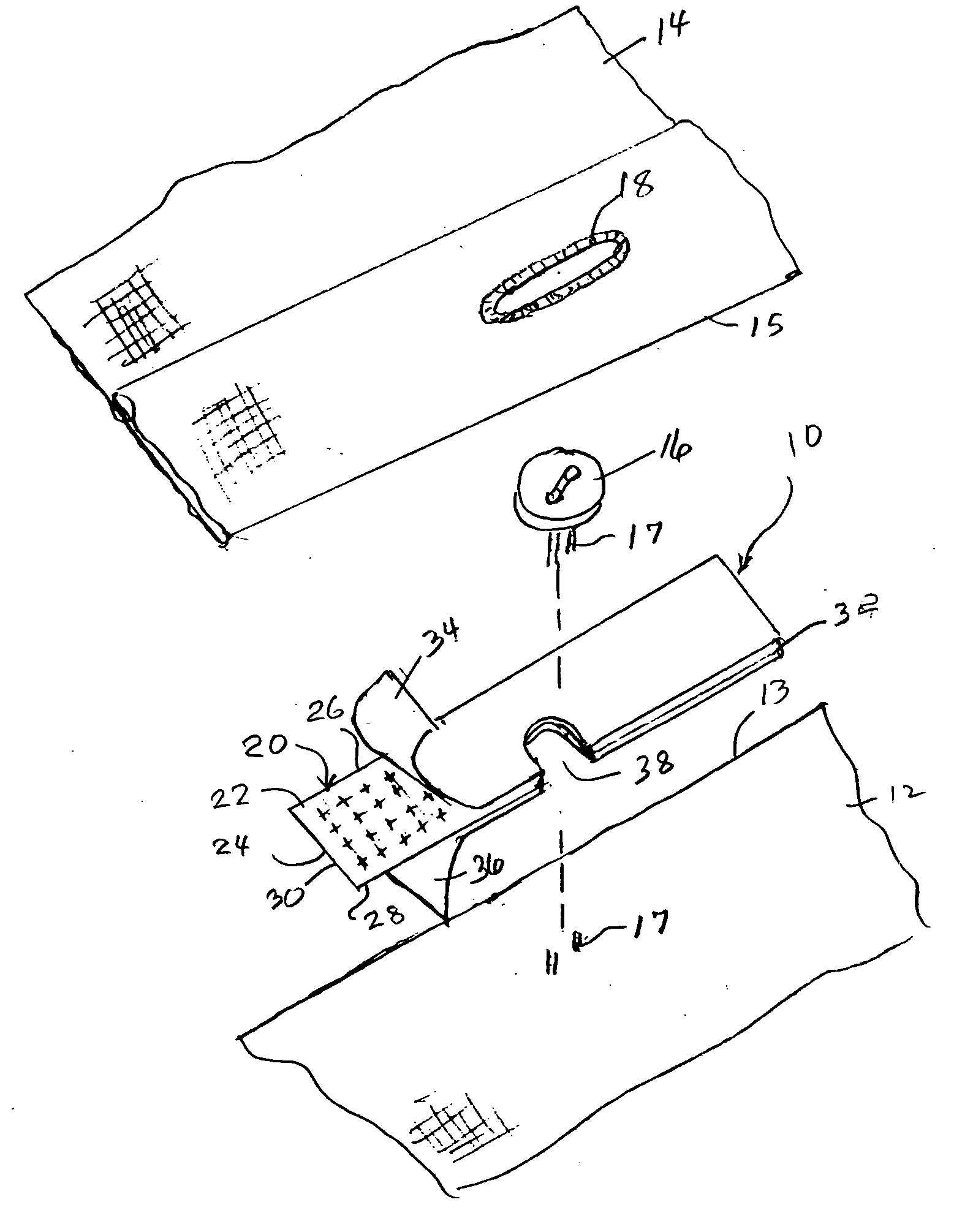
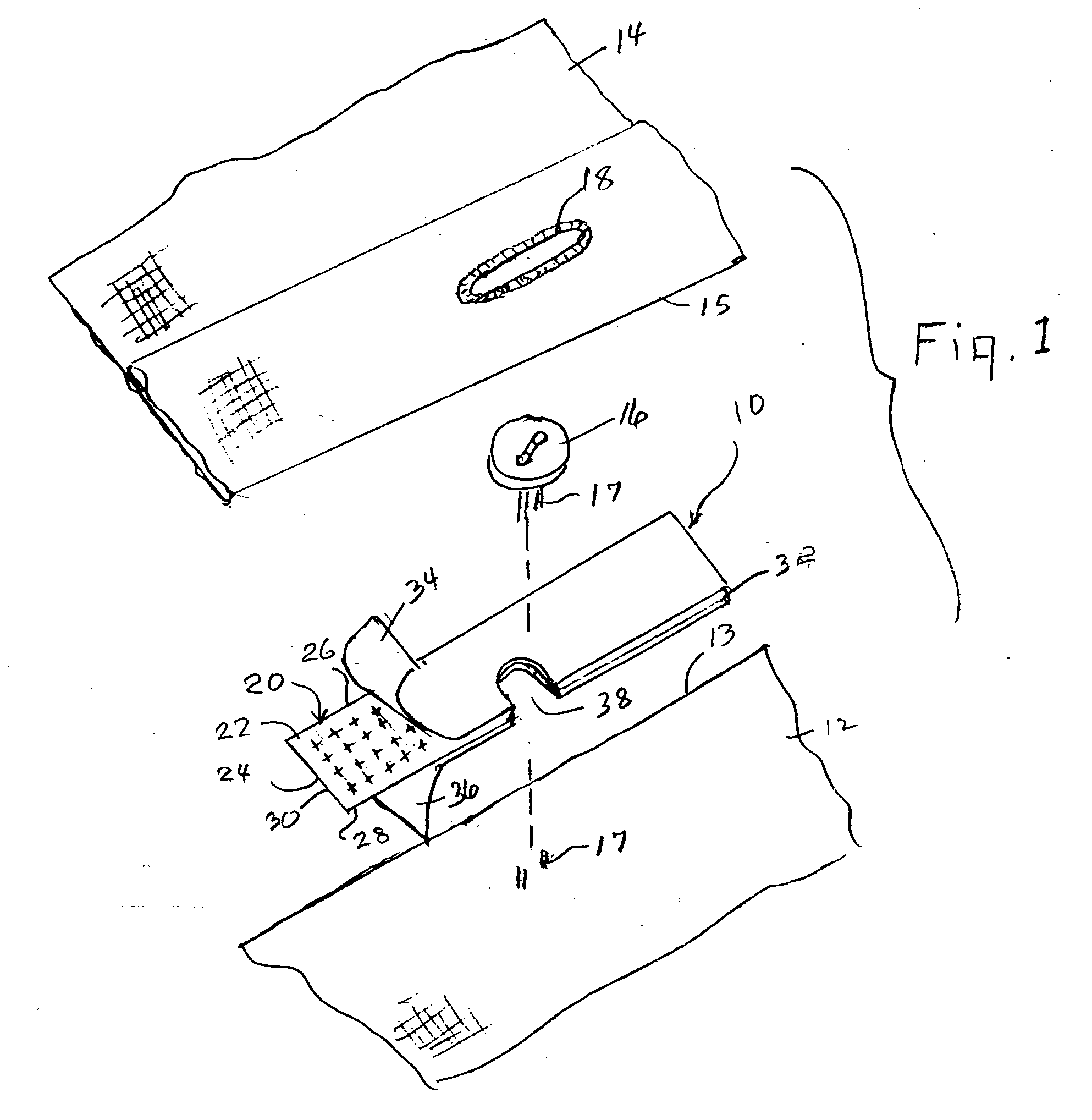
[0021] Referring now in more detail to the drawings, in which like numerals indicate like parts throughout the several views, FIG. 1 illustrates a blouse front closer 10 that is applied between a first or inner front panel 12 of a blouse and a second or outer front panel 14 of the blouse. The blouse includes a series of buttons, such as button 16, and buttonholes, such as buttonhole 18, and the outer front panel is connected to the inner front panel in the conventional way by passing the buttonhole 18 about the button 16.

[0022] As illustrated in FIG. 1, the blouse front closer 10 usually will be positioned against the outer surface of the inner front panel 12, adjacent button 16, and against the inside surface of the outer front panel 14.

[0023] The blouse front closer 10 of FIG. 1 includes an elongated connector strip 20 that has opposed first surface 22 and second surface 24, opposed longitudinal side edges 26 and 28, and opposed end edges 30 and 32.

[0024] Adhesive is applied to...


PUM


Abstract

A blouse front closer includes a strip connected by adhesive to the overlapping facing surfaces of the panels of the blouse preferably at and between the buttons of the blouse to hold the blouse closed. The intermediate segment of the strip may have no adhesive applied thereto for surrounding the button connector, and the blouse front closer may be formed of hook and loop patches for connecting the blouse panels together.

Description

CLAIM OF PRIORITY [0001] Applicant claims the benefit of U.S. Provisional Patent Application Ser. No. 60 / 710,711 filed Aug. 23, 2005.FIELD OF THE INVENTION [0002] This invention concerns an attachment to a blouse for holding closed the openings of a blouse at and between the buttons of the blouse to avoid the occurrence of inadvertent opening of the blouse. BACKGROUND OF THE INVENTION [0003] A typical woman's blouse is formed with a pair of opposed front panels with overlapping edges, with one of the front panels having a series of buttons, snaps or other connectors attached thereto by threads or other type connectors, and the second front panel having a series of buttonholes or other receivers for receiving the buttons, etc. of the first front panel. In some circumstances, the blouse panels tend to separate between the buttons or the buttons release from the button holes, forming an undesirable opening in the front of the garment. For example, the separation might be due to the blo...

Claims


Application Information

Patent Timeline
IPC IPC(8): A41D13/00
CPCA41F1/00
Inventor WHICKER, REBECCA
Owner WHICKER REBECCA
Why Eureka
Try Eureka