Eureka AIR delivers breakthrough ideas for toughest innovation challenges, trusted by R&D personnel around the world.

Gun trigger and hammer safety device

Inactive Publication Date: 2007-03-01
MC CLELLAN W THOMAS
View PDF19 Cites 0 Cited by
  • Summary
  • Abstract
  • Description
  • Claims
  • Application Information

AI Technical Summary

Benefits of technology

[0012] It is accordingly an object of the invention to provide a gun trigger and hammer safety device, which overcomes the herein-mentioned disadvantages of the heretofore-known devices of this general type, which functions as both a trigger guard and a hammer guard and is quick releasing.
[0014] In accordance with an added feature of the invention, the hammer locking end has first and second sides for form fitting to sides of the handgun. The first side has an inner side engaging one of the sides of the handgun and an outer side having a beveled protrusion. The beveled protrusion is provided for receiving a thumb force for assisting in removing the safety device after the safety device is installed on the handgun. Preferably, the beveled protrusion has a roughened surface for assisting in engaging a thumb of a user.
[0016] In accordance with another feature of the invention, the trigger locking end has protrusions defining a recess between the protrusions for form fitting the trigger locking end on the trigger guard. The protrusions extend below the physical structure of the trigger guard. The trigger locking end has a front face preventing a rearward movement of the trigger and a rear surface butting against the trigger guard. The front face is adapted to a shape of the trigger. The trigger locking end has cutouts formed therein. The cutouts save material costs and weight.

Problems solved by technology

The disadvantage of this type of device is that it must be unlocked with a key if firing is necessary.
Although this is effective in preventing a child from firing the gun, it may also inhibit proper use in an emergency situation while searching for the key.
The safety devices described so far have the added disadvantage that they may be readily seen making it apparent to the uninitiated or even a child that the weapon has been disabled.
Thus, any such safety device that is cumbersome to remove in an emergency situation is undesirable.
Concealed handguns constitute an additional hazard to the handgun user because the user is usually in an excited and adrenaline charged state when he / she is withdrawing the handgun in an emergency situation.
There is an increased risk of accidental discharge of the handgun and injury to the carrier of the handgun, when the handgun is grasped, and withdrawn rapidly from the pocket, holster or other concealment device.

Method used


Image

  • Gun trigger and hammer safety device
  • Gun trigger and hammer safety device
  • Gun trigger and hammer safety device

Examples


Embodiment Construction

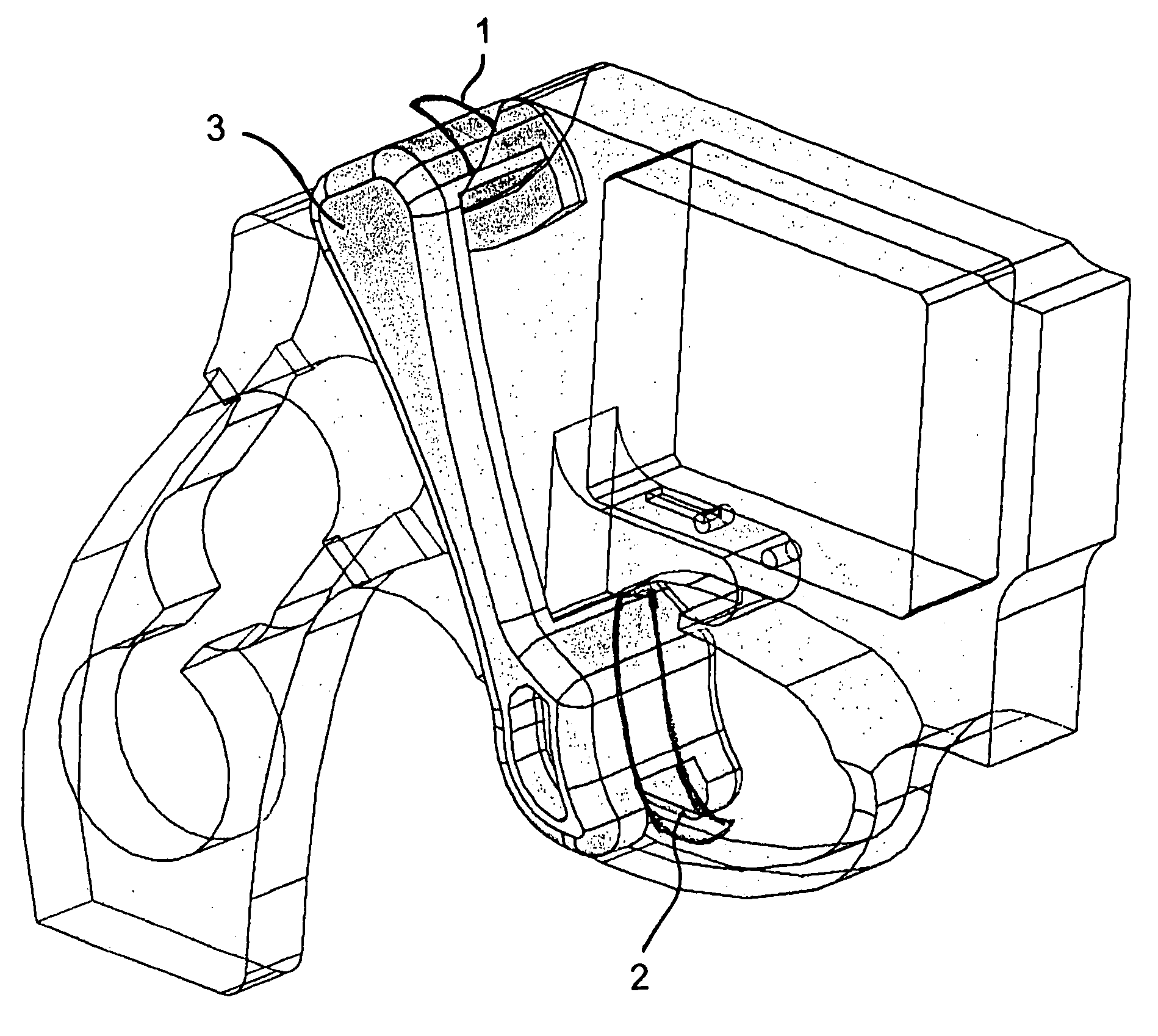
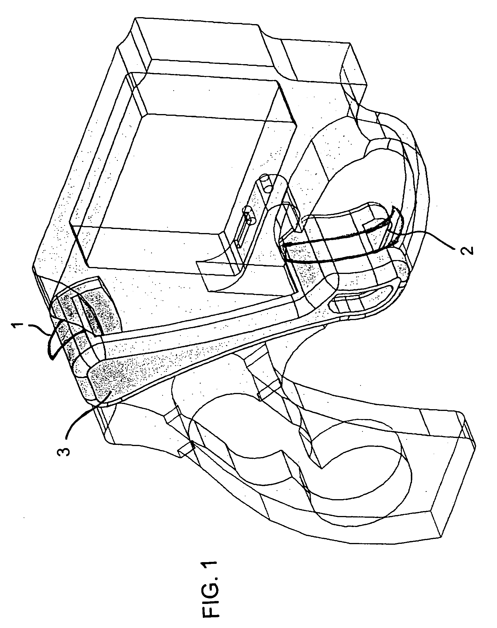
[0028] A double action handgun or revolver generally includes a frame, a barrel, a handgrip, a hammer, a trigger, and a trigger guard. The handgun further includes a rotatable chambered cylinder wherein a plurality of bullets are contained so that the handgun may be fired several times without reloading.

[0029] The term double action refers to the two-part movement of the trigger during operation. Depressing the trigger results initially in a reverse movement or cocking of hammer, which in its return movement, or firing motion, revolves the chambered cylinder and brings the next bullet in line for firing. In many guns today, the hammer is integrated into the frame and cannot be seen. The invention of course can work with handguns having the traditional hammer configuration and such a hammer 1 is shown in FIG. 1. The invention works with either type of hammer. In addition, the trigger 2 is only diagrammatically shown in FIG. 1 for clarity purposes.

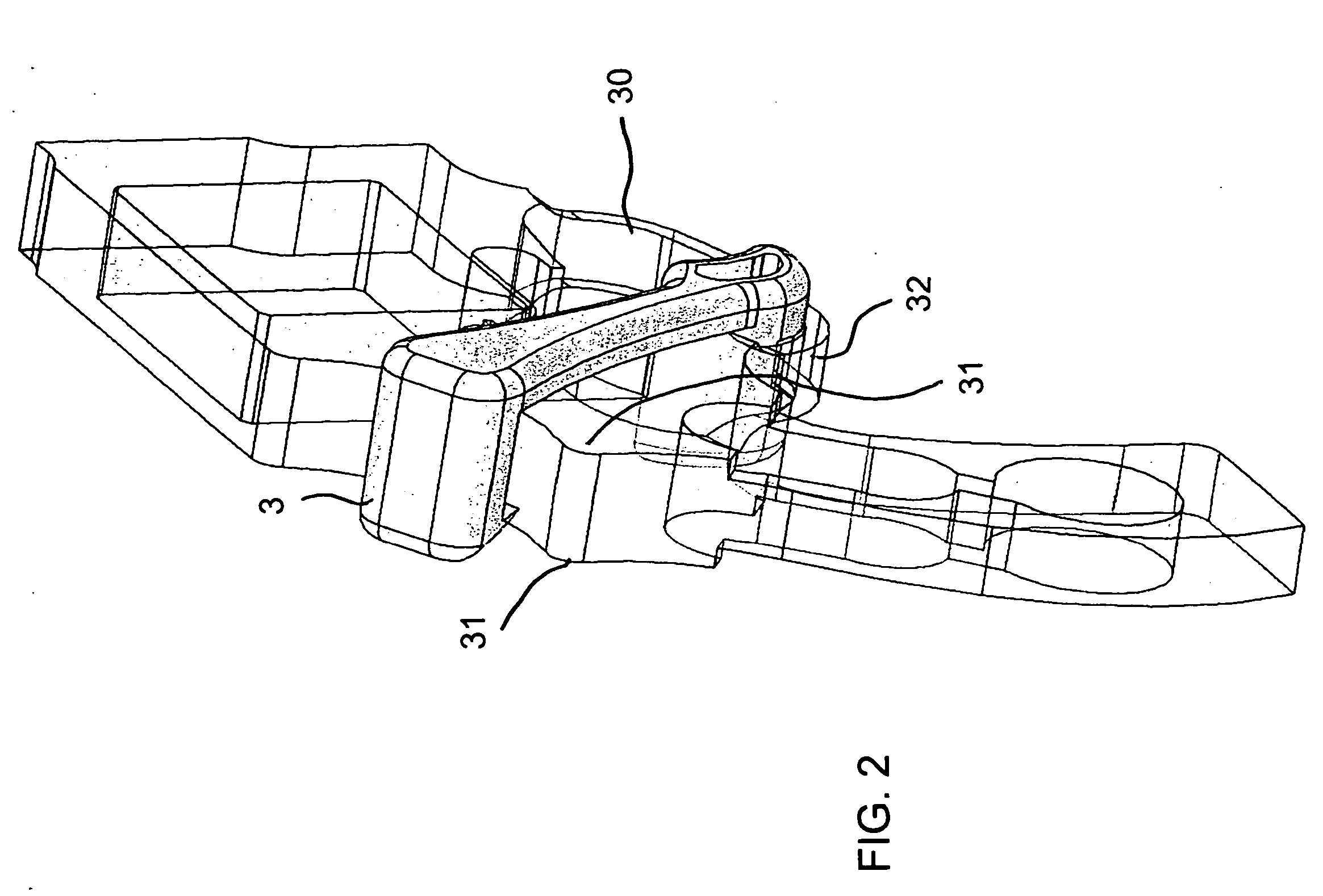
[0030] Since such double-action han...


PUM


Abstract

A safety device is provided for a handgun having a trigger, a hammer and a trigger guard. The safety device contains a hammer locking end for locking the hammer, a trigger locking end for locking the trigger, and a structural support member extending between the hammer locking end and the trigger locking end. The safety device thus locks both the trigger and the hammer and is releasably connected to the handgun.

Description

BACKGROUND OF THE INVENTION [0001] 1. Field of the Invention [0002] The invention relates, generally, to gun safety devices, and more specifically, it relates to a clip-on / clip-off gun trigger and hammer safety device. [0003] 2. Description of the Related Art [0004] Safety devices to prevent accidental firing of handguns are well known to those skilled in the art. Such safety devices are available in a variety of configurations. Trigger covers may be attached to a handgun to cover the entire trigger guard preventing access to the trigger. However, such safety covers must be attached by pins or screws and a special tool is required for release of the cover. An example of such a trigger cover is disclosed by U.S. Pat. No. 5,075,994 to Nishioka. Nishioka discloses a trigger cover including a locking device that is unlocked using a tool such as an Allen wrench or a key. [0005] Other such safety devices utilize a locking clamp that holds the trigger in a depressed position thereby preven...

Claims


Application Information

Patent Timeline
IPC IPC(8): F41A17/00
CPCF41A17/54F41A17/74
Inventor MC CLELLAN, W. THOMAS
Owner MC CLELLAN W THOMAS
Why Eureka
Eureka Blog
Learn More