Eureka AIR delivers breakthrough ideas for toughest innovation challenges, trusted by R&D personnel around the world.

High performance power device

a power device and high-performance technology, applied in the direction of printed circuit aspects, electrical apparatus construction details, transportation and packaging, etc., can solve the problems of high power circuits and/or densely packed circuits, electrical components used as part of power devices, can often generate significant heat during operation, and achieve high power. , the effect of/or baseplates, and reducing the temperature rise of coldplates

Active Publication Date: 2009-07-23
RAYTHEON CO
View PDF19 Cites 29 Cited by
  • Summary
  • Abstract
  • Description
  • Claims
  • Application Information

AI Technical Summary

Benefits of technology

[0009]Because of issues such as the device temperature rise, it would be advantageous to reduce the temperature rise as much as possible in as many areas as possible, such as the coldplate and / or baseplate of a DC / DC converter. Reducing coldplate and / or baseplate temperature rise permits the design of DC / DC converters having high power, which can help to reduce cost (e.g., replacing multiple lower power converters with a single higher power converter), meet future mission requirements that draw more power, and improve reliability, because the components will not be as thermally stressed. As described further in at least some embodiments of the invention described herein, fabricating the DC / DC converter power circuit card from a panel that has pyrolytic graphite (PG) inserts helps to provide at least some of these advantages, as well as many other advantages described herein. PG is particularly advantageous because it has an in-plane thermal conductivity that is ten times greater than that of aluminum. This property also can help to reduce the component to edge temperature rise in devices that use PG.
[0010]In one aspect, the invention provides a power card usable for a DC / DC converter, where the power card has a baseplate made of a material that is both electrically and thermally conductive and which has one or more inserts of annealed pyrolytic graphite (PG) embedded therein. Doing this helps to transfer heat generated by electrical components coupled to the power card, such as the high-heat flux electrical components and / or the other electrical components, away from the components much more effectively than is done using merely a conductive layer or a baseplate that does not have PG inserts. Because the power card baseplate also is electrically conductive, the power card baseplate not only improves thermal performance, the power card baseplate can perform two functions at once and save weight and cost in the power card, thereby improving performance in and saving weight and cost of the resultant DC / DC converter 10, as well. If the power card has embedded PG inserts, as described herein, a separate heat sink coupled to the power card is not needed to maintain desired thermal performance. Optionally, however, the power card can be coupled to a cold plate or other heat sink, in a next higher assembly, to further distribute and dissipate the heat.

Problems solved by technology

Electrical components, especially those used as part of power devices, can often generate significant heat during operation.
This air cooling can be insufficient, however, for high power circuits and / or densely packed circuits.
An aluminum baseplate is considerably better at transferring heat to the edges of a baseplate than dielectric material alone, but aluminum still has some thermal limitations.
Because of aluminum's thermal limitations, in some instances it is necessary to break up a single higher power DC / DC converter into multiple lower power designs, resulting in higher cost and weight.
However, heat sinks or cold plates with added graphite and / or aluminum to increase the thermal conductivity of the heat sink or cold plate increase the size, weight, and cost of the device.
In higher power DC / DC converters, that temperature rise alone can exceed the total allowable temperature rise, and a more expensive alternate design must be implemented, a significant portion of the allowable temperature rise from the component locations to the cooled edges comes transformer and output rectifier.

Method used


Image

  • High performance power device
  • High performance power device
  • High performance power device

Examples


Embodiment Construction

[0047]In addition to the various embodiment or embodiments disclosed below, this invention is capable of other embodiments and of being practiced or being carried out in various ways. For example, the invention is applicable to virtually any electrical device that has components that generate heat, and is not limited to power devices or DC / DC converters. Various embodiments of the invention include (but are not limited too), DC / AC converters, AC / DC converters, AC / DC converters, power supplies, and the like. Thus, it is to be understood that the invention is not limited in its application to the details of construction and the arrangements of components set forth in the following description or illustrated in the drawings.

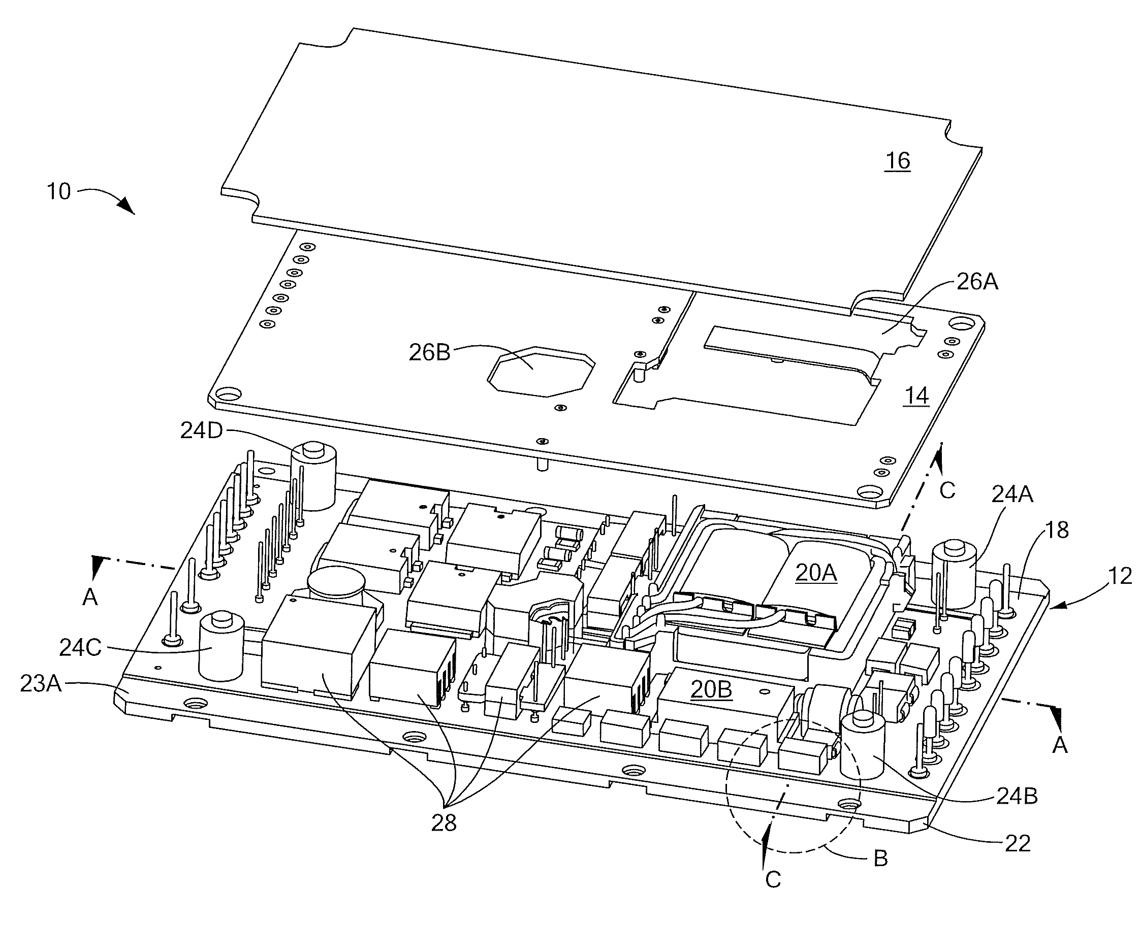
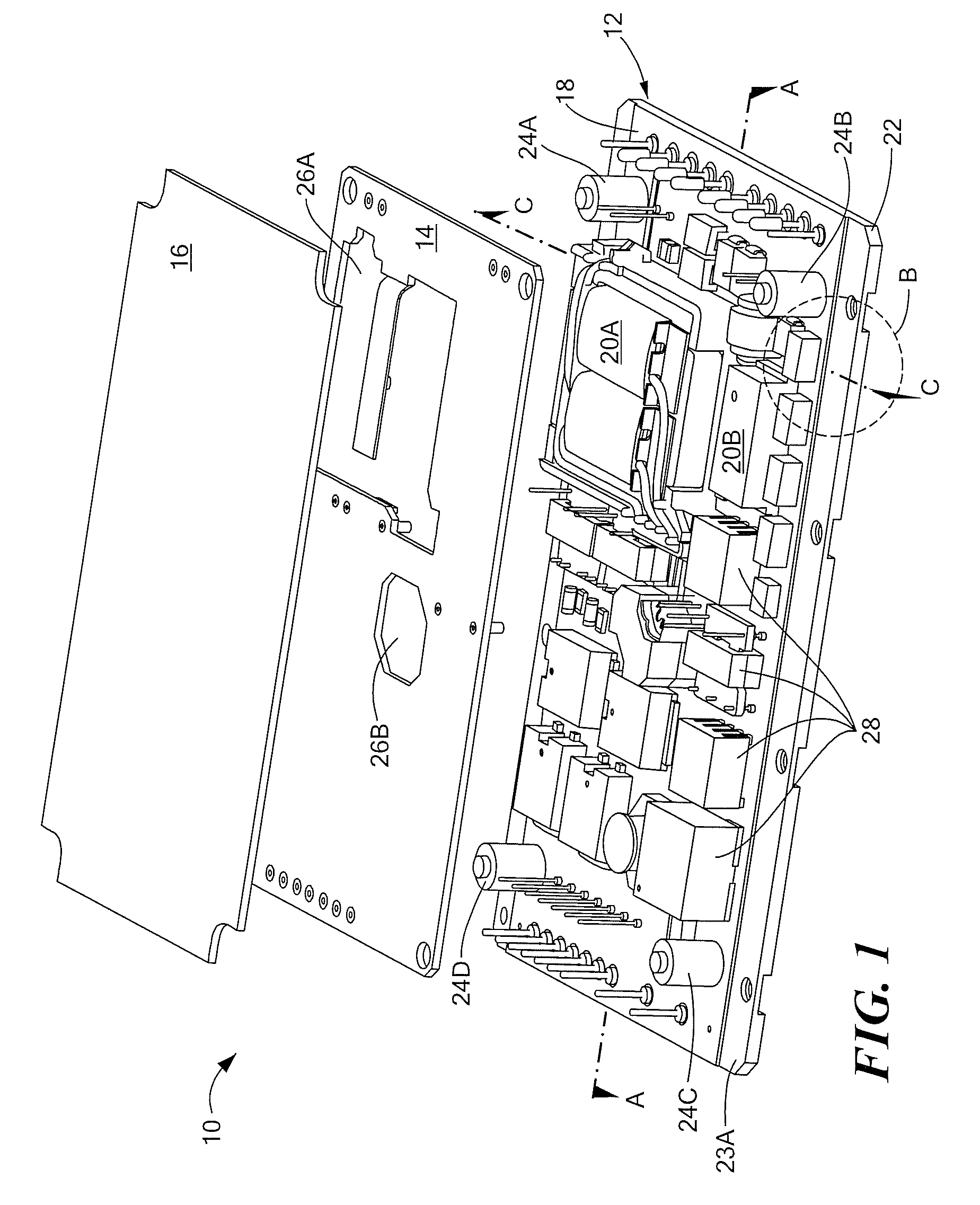
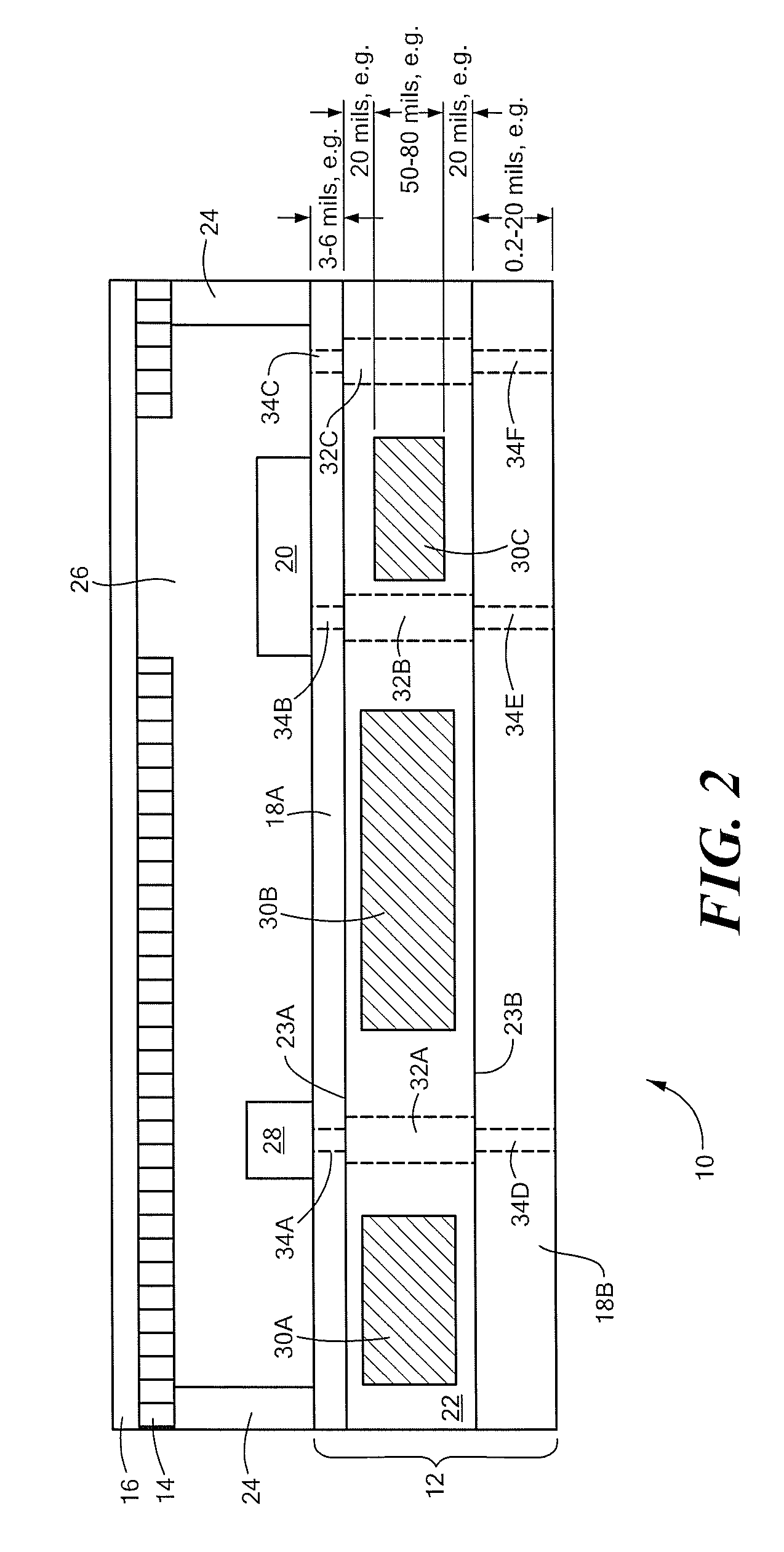
[0048]FIG. 1 is an exploded three-dimensional view of a DC / DC converter assembly 10 in accordance with a first embodiment of the invention. FIG. 2 is a cross-sectional side view of the DC / DC converter assembly of FIG. 1, taken along line A-A. Referring to FIGS. 1 an...


PUM

PropertyMeasurementUnit
thicknessaaaaaaaaaa
thicknessaaaaaaaaaa
anglesaaaaaaaaaa

Abstract

A printed circuit board (PCB) assembly is provided. The PCB assembly is adapted for mounting at least one heat-generating electrical device and providing integrated heat dissipating capability to dissipate heat generated by the electrical device. The PCB assembly has a top surface and a bottom surface and comprises a signal carrying layer and an insert of pyrolytic graphite (PG). The signal carrying layer, disposed between the top surface and the bottom surface, comprises a material that is both thermally conductive and electrically conductive (such as at least one of aluminum, copper, and silver and alloys thereof) and has at least a portion lying in a first plane. The insert of PG is disposed within at least a portion of the first plane of the signal carrying layer, is in thermal contact with the signal carrying layer, and is constructed and arranged to have its greatest electrical conductivity in the first plane. Optionally, a conductive via can be formed in portions of the signal carrying layer not occupied by the insert of PG, where the conductive via operably couples a first side of the signal carrying layer to a second side of the signal carrying layer.

Description

CROSS-REFERENCE TO RELATED APPLICATIONS[0001]This application is related to U.S. Pat. No. 6,903,931 to McCordic et al., entitled “Cold Plate Assembly,” the contents of which are hereby incorporated by reference.FIELD OF THE INVENTION[0002]Embodiments of the invention generally relate to power devices such as DC-DC converters. More particularly, the invention relates to a power device assembly that integrates both signal carrying and thermal cooling functions into a single circuit card.BACKGROUND OF THE INVENTION[0003]Electrical components, especially those used as part of power devices, can often generate significant heat during operation. Because high temperatures can degrade the performance of (or even cause the failure of) many electrical components, assemblies that use such heat-generating components must be able to dissipate heat well enough to maintain acceptable performance of the electrical component.[0004]Many different techniques can be used to provide cooling of electrica...

Claims


Application Information

Patent Timeline
Patent Type & Authority Applications(United States)
IPC IPC(8): H05K7/20H05K3/00
CPCH05K1/0204H05K1/056H05K1/144Y10T29/49124H05K7/209H05K2201/0323H05K3/0061Y10T428/249999Y10T428/249994
Inventor ELLSWORTH, JOSEPH R.MARTINEZ, MICHAEL P.PEREIRA, STEPHEN J.
Owner RAYTHEON CO
Why Eureka
Eureka Blog
Learn More