Eureka AIR delivers breakthrough ideas for toughest innovation challenges, trusted by R&D personnel around the world.

Thermally efficient busway

Inactive Publication Date: 2013-01-03
SCHNEIDER ELECTRIC USA INC
View PDF8 Cites 5 Cited by
  • Summary
  • Abstract
  • Description
  • Claims
  • Application Information

AI Technical Summary

Benefits of technology

This patent describes a solution for lowering the temperature of a busway and joint pack used to connect multiple busway sections together. By using pads made of thermally conductive but electrically insulating material, the temperature of the busbar conductors and joint packs is reduced, allowing for less copper usage, saving weight and cost. The pads can conform to the uneven surfaces of the busbar conductor and insulating sleeve, and are removable without leaving any exposed metal. The technical effect of this solution is reduced temperatures, saving materials and weight, and improved reliability and performance of the busway system.

Problems solved by technology

One way to cool conductors is to add more copper by making them thicker or wider, but copper is expensive and more of it adds bulkiness and heft to the busway overall.
This is generally because of additional contact resistance at the points of contact which generate increased power losses at the points of contact.
The increased power loss coupled with the thermal resistances for the busway system usually cause an increase in temperature at the points of contact.
These joint packs can also become very hot as they transfer electrical current from one busway to the next.

Method used


Image

  • Thermally efficient busway
  • Thermally efficient busway
  • Thermally efficient busway

Examples


Embodiment Construction

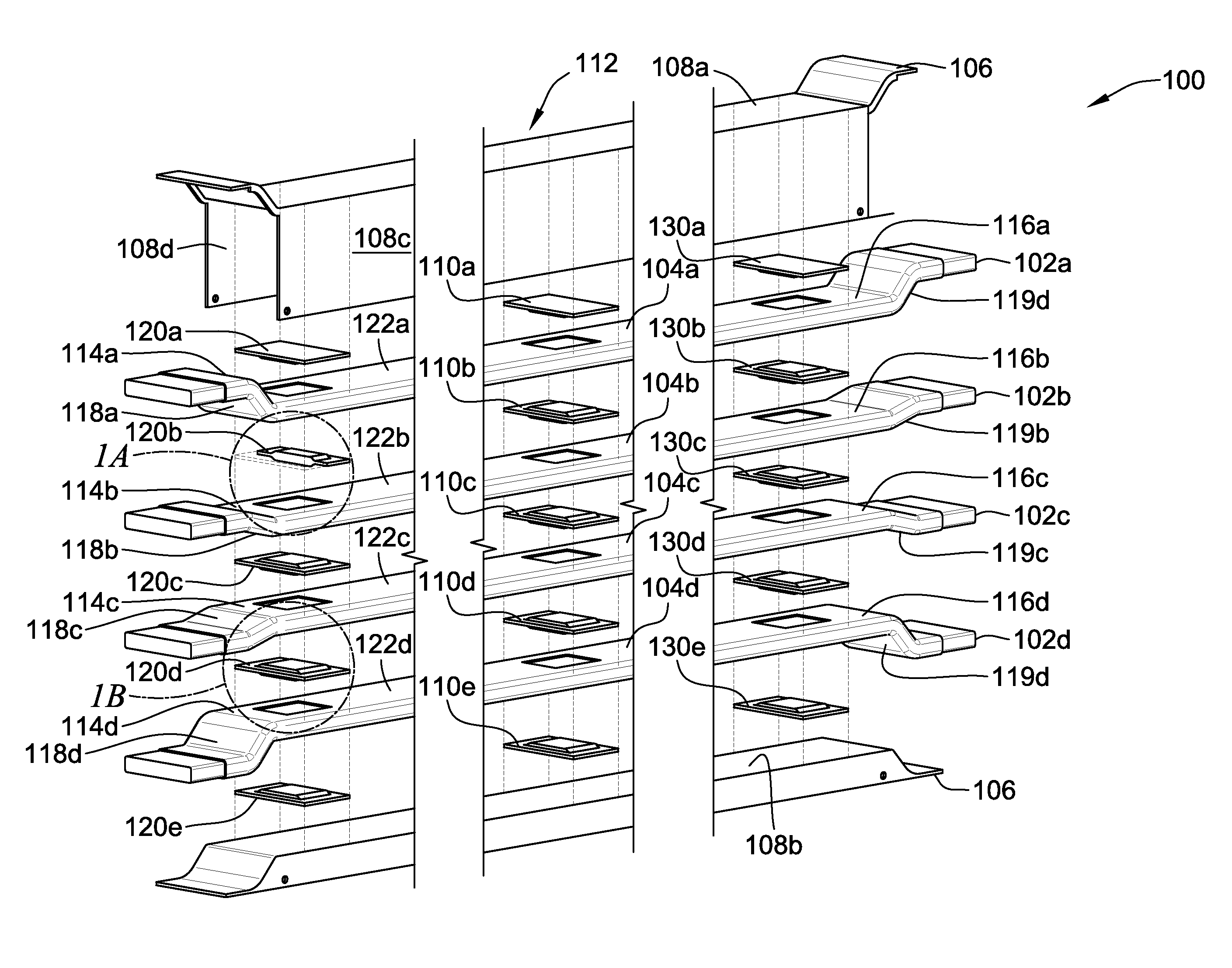
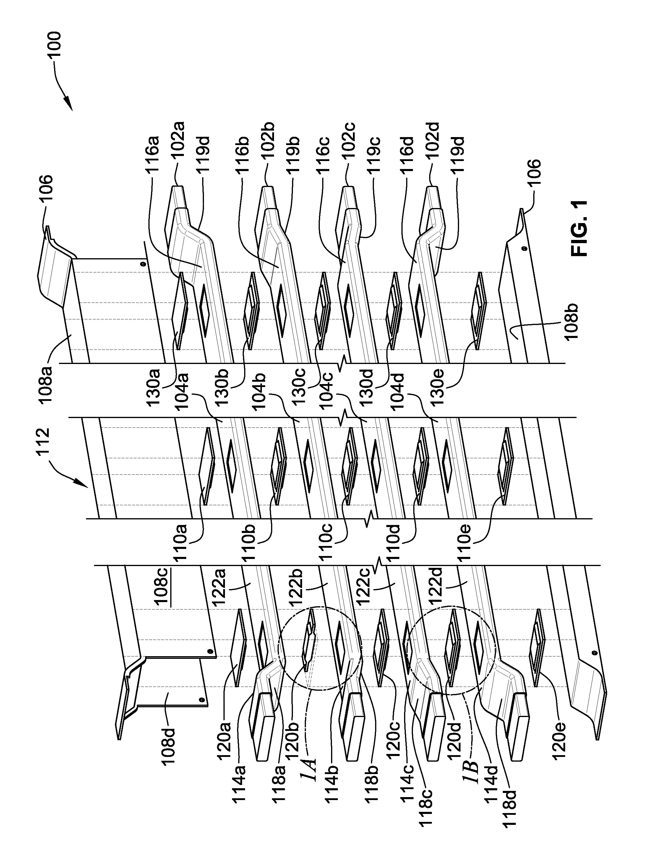
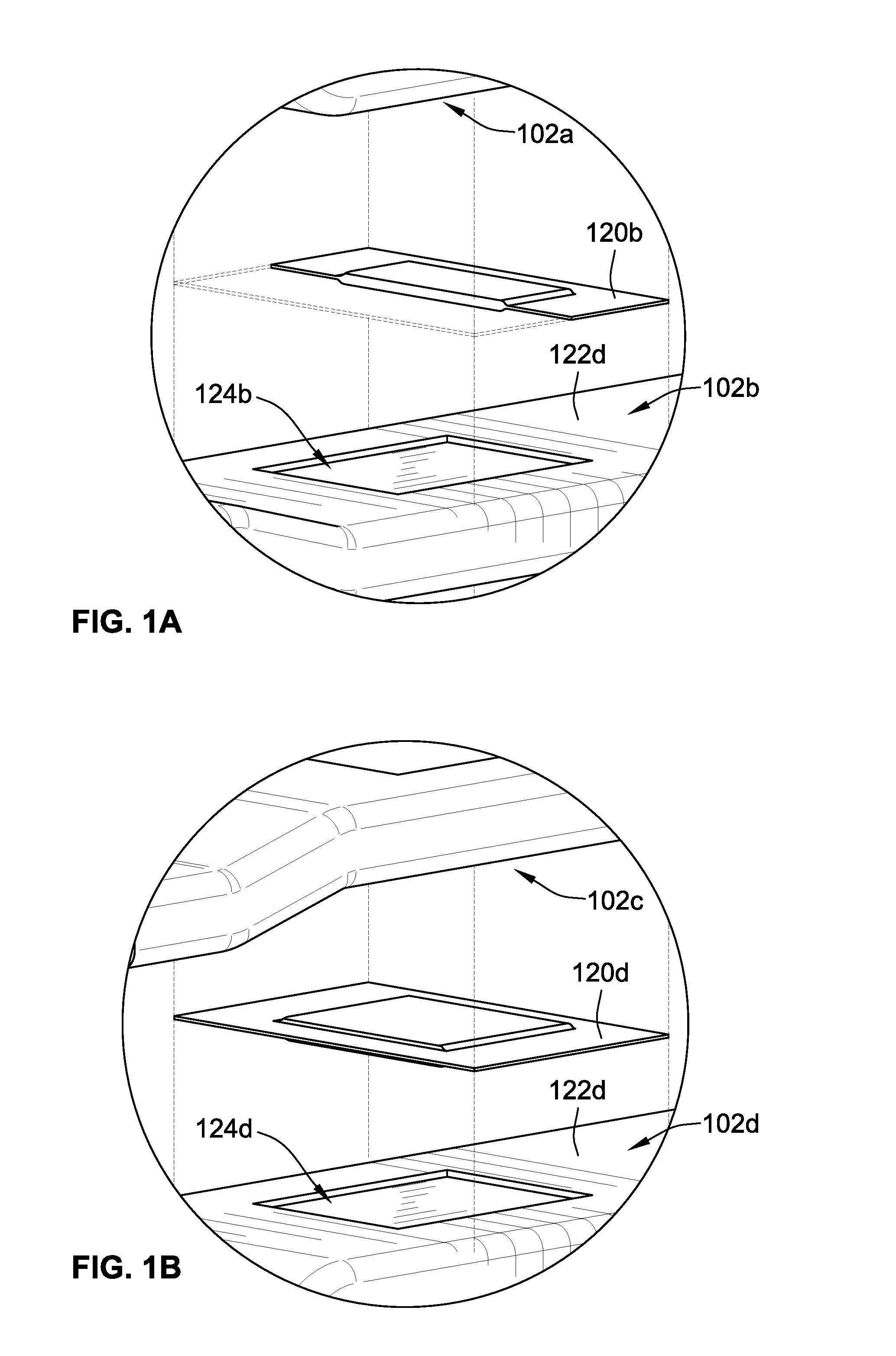
[0022]FIG. 1 is a perspective illustration of a busway section 100 shown in exploded form for ease of illustration. The busway section 100 includes four electrically conductive busbar conductors 102a,b,c,d stacked on top of one another to form a stack 101 (see FIG. 2). Each of the busbar conductors 102a-d has an elongated straight section 104a-d, respectively, and are composed of an electrically conductive material, such as a material that includes copper. Each busbar conductor 102a-d includes an electrically insulating sheet or sleeve 122a-d that surrounds or wraps around the busbar conductors 102a-d and is present in all areas where any busbar conductors 102 is in physical contact with an adjacent busbar conductor 102.

[0023]In this illustrated example, four busbar conductors 102 are shown, with three of the conductors 102 conventionally carrying a different phase of electricity (typically labeled A, B, and C to designate that each phase of current lags the other by 120 degrees), a...


PUM


Abstract

A busway having multiple busbar conductors and pads composed of a thermally conductive, insulating material (TCIM) sandwiched in between each of the conductors and between the outermost conductors and the inside of the busway housing. The busway preferably includes three sets of TCIM pads, one set in the center of the busway, and a set at either end of the busway where a joint pack is installed to join multiple sections of busway sections together. The insulating material on the conductors has a cutout to expose the bare metal of the conductors, and a TCIM pad is placed directly on the exposed metal through the cutout, to form a thermal conduit between the busbar conductors to the metal housing of the busway, thereby reducing the temperatures of the busbar conductors and the joint pack during normal operation in which hundreds or thousands of amps of current are carried through the busway sections.

Description

FIELD OF THE INVENTION[0001]The present disclosure relates to busway sections used in electrical distribution systems.BACKGROUND[0002]A busway as used in an electrical distribution system, which can include a switchboard, switchgear, or motor-control center, includes a housing enclosing a stack of insulated electrical phase conductors called busbars, in prefabricated sections. The sections are joined together to carry the different phases of electrical current from a source of energy to one or more loads. The conductors are typically made of copper and can carry hundreds or even thousands of amps of current. As a result, these conductors get very hot and efforts are made to cool them so that they meet thermal requirements set by a certification organization such as Underwriters Laboratory (UL). One way to cool conductors is to add more copper by making them thicker or wider, but copper is expensive and more of it adds bulkiness and heft to the busway overall.[0003]There are two type...

Claims


Application Information

Patent Timeline
IPC IPC(8): H02B1/20
CPCH02G5/005H02G5/10H02G5/06H02G5/007
Inventor RODRIGUES, CARLTON R.ORTIZ, EDGAR AVALOSO'LEARY, TIMOTHY P.
Owner SCHNEIDER ELECTRIC USA INC
Why Eureka
Eureka Blog
Learn More