Free work pressing device for sewing machine

a sewing machine and work pressing technology, applied in the direction of feeders, embroidering machines, textiles and paper, etc., can solve the problems of preventing the efficient stitching operation, high sewing machine maximum rotation speed, and violent up and down movement, and achieve the effect of simple structure and maximum rotation speed

Active Publication Date: 2007-03-01
JANOME CORP
View PDF7 Cites 11 Cited by
  • Summary
  • Abstract
  • Description
  • Claims
  • Application Information

AI Technical Summary

Benefits of technology

[0010] The work pressing device for sewing machine of the invention may allow the sewing machine to have a maximum rotation speed which may be set rather high for efficient stitching operation without noises. This is because the work pressing device has the slide shaft which is not connected to the needle bar which is axially reciprocated for stitching the work, in contrast to the conventional work pressing device which has the slide shaft operatively connected to a pin of the needle holder of the needle bar so as to be axially reciprocated in association with the axial movement of the needle bar, the pin striking the slide shaft each time the needle bar goes up to move up the slide shaft and inevitably producing loud bump noises.
[0011] Further the work pressing device for sewing machine of the invention is very simple in structure because the adjust mechanism includes the adjust screw member which is in threaded engagement with the slide shaft at the upper part thereof so that the adjust screw member may be rotated to adjust the vertical position of the work pressing foot relative to the work to be stitched, the work pressing foot being secured to the lower end of the slide shaft.

Problems solved by technology

However, since the slide shaft member disclosed in the Japanese Utility Model Registration No. 62-32549 is moved up and down by the needle bar that is driven to move up and down, the up and down movement is rather violent and produces loud noises.
It is, therefore, problematical to set high the maximum rotation speed of sewing machine.
Such limitation will often prevent the efficient stitching operation.
Further since the work pressing foot is normally pressed against the needle plate by means of a spring, it is often difficult to stitch a rather thick work. which is placed between the work pressing foot and the needle plate.

Method used


Image

  • Free work pressing device for sewing machine
  • Free work pressing device for sewing machine
  • Free work pressing device for sewing machine

Examples


Embodiment Construction

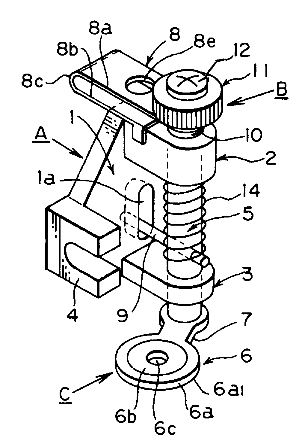
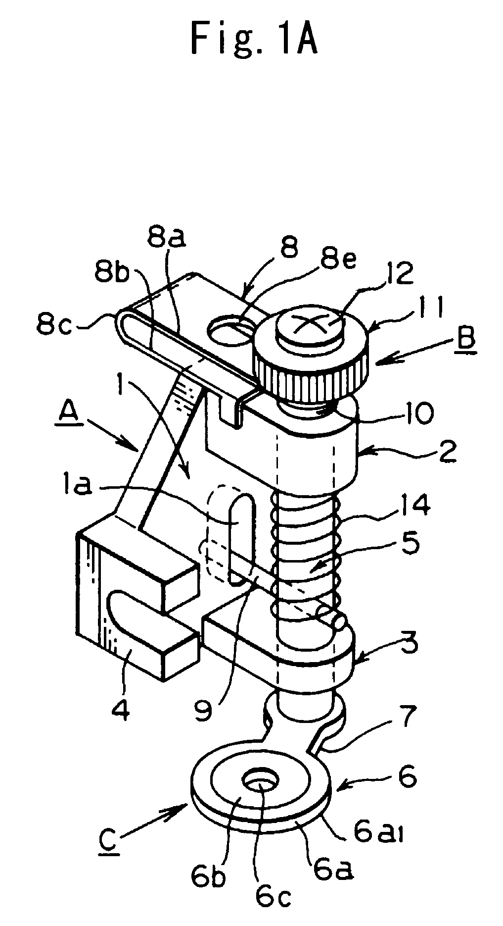
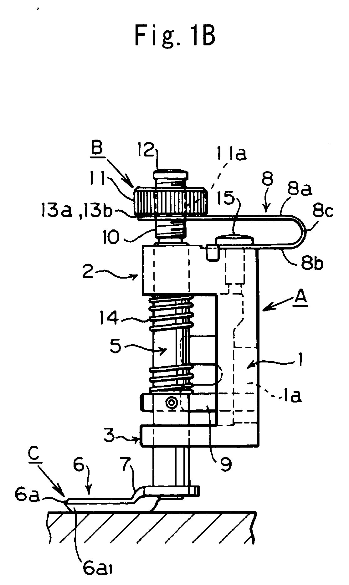
[0021] The invention will be described in detail in reference to the attached drawings. As particularly shown in FIG. 1, the free work pressing device for sewing machine according to the invention is substantially composed of a holding portion A, a slide shaft 5, an elastic member 14, an adjust mechanism B and a work pressing foot C. As shown in FIG. 2A, the holding portion A includes a holder body 1 of flat plate that is formed with an upper holder 2 and a lower holder 3.

[0022] The upper holder 2 and the lower holder 3 are formed as laterally extended from the vertical flat plate 1 and have a through hole 2a and a through hole 3a respectively for supporting the slide shaft 5 so that the same may be slidingly moved in the axial direction. Further the holder body 1 is formed with a connecting portion 4 by which the holder body 1 is connected to a presser bar 16 of sewing machine which is arranged adjacent a needle bar in parallel therewith. The holder body 1, the upper holder 2, the...


PUM


Abstract

Disclosed is a free work pressing device for sewing machine which is simple in structure and smooth in operation. As to the variation in the thickness of the work (18), the work pressing foot (C) is smoothly movable as yielding up and down in dependence upon the variation in the thickness of the work against and under the control of the elastic member (14).
The free work pressing device sewing machine comprises a holding portion (A) for mounting the free work pressing device to the presser bar (16) of sewing machine, a slide shaft (5) supported by the holding portion (A) and being slidingly movable in the axial direction, a work pressing foot (C) secured to the lower end of the slide shaft (5), an elastic member (14) for normally pressing the slide shaft (5) axially in the downward direction relative to the holding portion (A), an adjust mechanism (B) for adjusting the vertical position of the work pressing foot (C) relative to the work (18) which is to be stitched.

Description

BACKGROUND OF THE INVENTION [0001] 1. Field of the Invention [0002] The present invention relates to a free work pressing device for sewing machine and more particularly relates to a work pressing device which is used in combination with a sewing machine in case so called the free kilt stitching operation is performed by use of a sewing machine. The free work pressing device is very simple in structure and very quiet in operation and is adapted to variation in the thickness of the work to be stitched. [0003] 2. Description of the related Art [0004] So far it has been prevalent to perform the free kilt stitching operation wherein the work is moved by hand under the work pressing foot in optional directions relative to the machine needle while the sewing machine is continuously driven. In the free kilt stitching operation, the work pressing device is something different from the one which is used in the normal stitching operation. The conventional work pressing device that is used for...

Claims


Application Information

Patent Timeline
Patent Type & Authority Applications(United States)
IPC IPC(8): D05B29/00
CPCD05B29/00
Inventor SHOMURA, EIICHIKOIKE, MIKIOTAOKA, MASAFUMI
Owner JANOME CORP
Why Eureka
Try Eureka