Multi-position rotary actuator controlled by a fluid

a rotary actuator and fluid technology, applied in the direction of valve operating means/release devices, gearing, servomotors, etc., can solve the problems of not negligible leakage rate in compressed air, unacceptable, and relatively complicated overall device implementation, so as to improve sealing performance, less leakage of control fluid, and good sealing

Active Publication Date: 2018-12-13
OUT & OUT CHEM
View PDF10 Cites 1 Cited by
  • Summary
  • Abstract
  • Description
  • Claims
  • Application Information

AI Technical Summary

Benefits of technology

[0016]The first and second hydraulic cylinders of the device of the invention are linear. The latter have a degree of a seal that is higher than that of rotary hydraulic cylinders with vanes that use a control fluid. In the end, the device of the invention has less leakage of control fluid. As linear hydraulic cylinders have a better seal than rotating hydraulic cylinders, it is not necessary to provide additional sealing shells with the device of the invention, or to use highly elaborated sealing parts. With the device of the invention, it is indeed possible to have good sealing performance by using simple sealing elements, such as O-rings, which are available of the shelf and are inexpensive. The manufacture of the device of the invention also requires fewer precautions when assembling the various elements for the same degree of sealing. Furthermore, it is easier to manufacture linear hydraulic cylinders than rotating hydraulic cylinders. In particular, it is simpler to manufacture linear hydraulic cylinders oneself than rotating hydraulic cylinders. It is there possible to avoid purchasing commercial hydraulic cylinders with the device of the invention and no longer be dependent on suppliers. These different reasons make it possible to have a control device that is simple to manufacture and to implement with respect to the device described in WO2013 / 127439 A1.
[0017]The device of the invention has other advantages. As it is easier to manufacture and as it requires less parts dedicated to obtaining high levels of a seal, the device of the invention is less expensive. It also makes it possible to work with lower pressures for the control fluid. By way of example, the inventors have found that with 4.5 bar of pressure, it is possible with the device of the invention to have an output torque equivalent to the device of WO2013 / 127439 A1 used with 6 bar; which is about a 25% reduction for the same space occupied. This aspect also facilitates the design of the device of the invention. There is no need for elaborate control logic for controlling the device of the invention. Each hydraulic cylinder can have only two configurations or two operating states. These two configurations can be referred to as ‘input rod / output rod’ or ‘IN / OUT’. The control device of the invention makes it possible to impose rotations in both directions and not only in a single direction. Thanks to this aspect, the device of the invention can be used in many applications. The device of the invention takes up little space. It can be used for controlling valves in corrosive, radioactive, wet, compact environments. It is also not necessary to provide electromagnetic shielding in order to protect electronic elements such as sensors for example.
[0018]The device of the invention claimed has other advantages in relation to document US 2001 / 0029835 A1 in which the device requires the interlocking of the system for converting linear motion into rotary motion with a piston in the same casing as well as the supply with fluid of a chamber of a piston through a second chamber. The device of the invention claimed requires four dynamic seals while the device of US 2001 / 0029835 A1 requires six dynamic seals. Reducing the number of dynamic seals makes the device more reliable in terms of a seal and simpler in terms of the manufacture thereof and of the assembly thereof.
[0019]The device of the invention claimed has four chambers provided with a fluid pressure control in order to be able to actuate the pistons of the hydraulic cylinders independently of one another. The four chambers of the device of the invention are all different and separate from one another and supplied independently by the control fluid. This has a certain advantage with respect to document US 2001 / 0029835 A1 which has only three chambers allowing for the control of two pistons. It as such appears that the two pistons cannot be controlled independently for all of the rotation movements of the output shaft. An independent control of the drives is particularly sought for the valve control in order to have hydraulic cylinder movements that are well controlled for a conversion into a rotary movement of which the angular rotation speeds are substantial.
[0020]The device of the invention could be called an activator or actuator for one or several valves. Preferably, the device of the invention therefore comprises, along a longitudinal direction, the following elements in the following order: the first hydraulic cylinder, the second hydraulic cylinder and the member for converting. A member can as such be obtained for converting and therefore a device according to the invention that is particularly simple and compact. The rotating element included in the member for converting is separate from the first piston.

Problems solved by technology

The leakage rate in compressed air is not negligible and for certain applications, it is not acceptable.
On the other hand, its various elements are relatively difficult to manufacture and the overall device is relatively complicated to implement.
The complex architecture that in particular the interlocking has of a hydraulic cylinder and of an element for converting linear motion into rotary motion appears difficult to implement due to the problem with the seal on the system for converting linear motion into rotary motion.

Method used


Image

  • Multi-position rotary actuator controlled by a fluid
  • Multi-position rotary actuator controlled by a fluid
  • Multi-position rotary actuator controlled by a fluid

Examples


Embodiment Construction

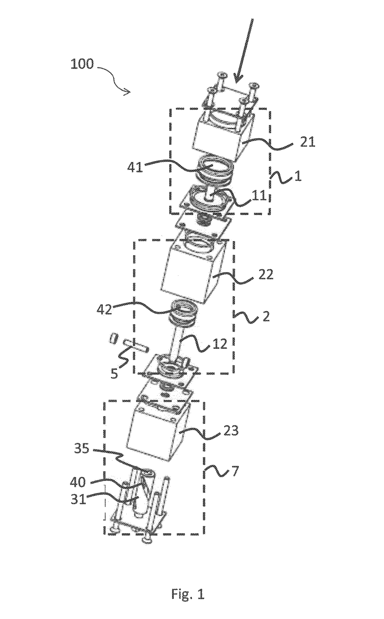
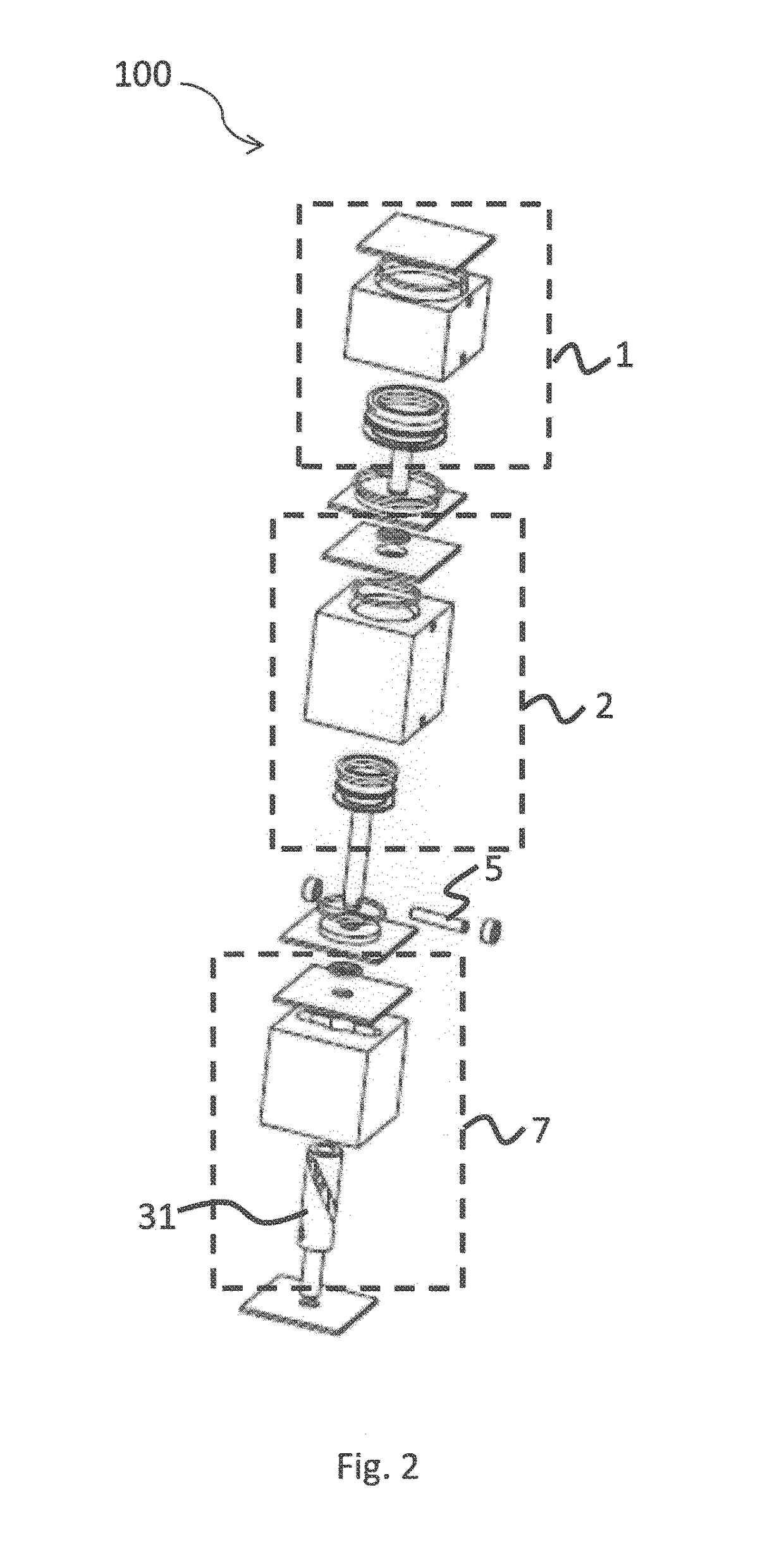
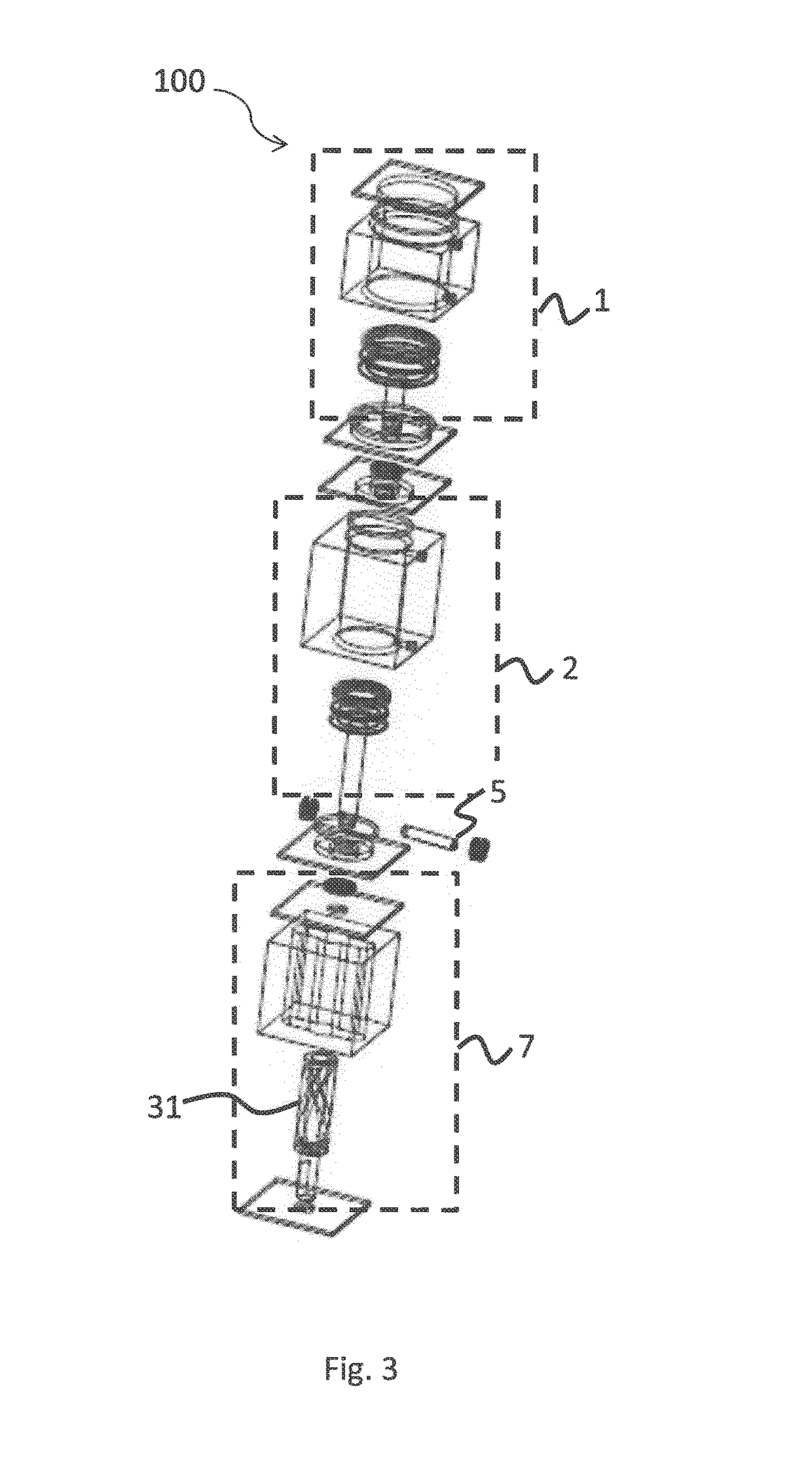
[0041]FIGS. 1 to 3 show different views of an example of the device 100 according to the invention. Along a longitudinal direction, symbolised by an arrow in FIG. 1, the device 100 comprise a first 1 and a second 2 hydraulic cylinder. These two hydraulic cylinders (1, 2) are coupled in such a way that a configuration (or operating state) of the first hydraulic cylinder 1 can influence a configuration (or operating state) of the second hydraulic cylinder 2. It can also be said that the first and second hydraulic cylinders (1, 2) are coupled in such a way that the first 1 is able to influence the second 2 and more particularly an operating state of the second hydraulic cylinder 2. For example, the first and second hydraulic cylinders (1, 2) can be mechanically coupled. This shall be seen more clearly during the description of the operation of the device 100 of the invention which will be done with FIG. 5.

[0042]The first 1 (respectively second 2) hydraulic cylinder is a linear hydrauli...


PUM


Abstract

Actuators and devices are provided for imparting a rotary movement and comprising in a longitudinal direction first and second hydraulic cylinders, characterised in that the first driver is a linear hydraulic cylinder comprising a first piston, and that the second driver is a linear hydraulic cylinder comprising a second piston, and in that the devices include a member for converting linear motion into rotary motion in order to convert a translation movement of the second piston into a rotary movement.

Description

TECHNICAL FIELD[0001]The invention relates to a device for imparting a rotary movement, more preferably with several angular stop positions defined. Such a device can be for example used to control one or several valves. The inventors also propose a system for controlling the passage of a fluid in a duct and a machine for synthesising or purifying elements comprising the control device of the invention.PRIOR ART[0002]Devices for imparting a rotary movement are known, used for example for controlling valves.[0003]WO2013 / 127439 A1 describes for example a compressed air device for controlling valves. This device comprises a first and a second rotary hydraulic cylinders with vanes connected together by mutual interlocking. These two rotary hydraulic cylinders are generally supplied with compressed air as a control fluid. The use of the two rotary hydraulic cylinders of this device makes it possible to impose three positions of a valve to be controlled, for example three different orient...

Claims


Application Information

Patent Timeline
Patent Type & Authority Applications(United States)
IPC IPC(8): F16K31/163F15B15/06F15B15/14F16H25/18F16K31/122
CPCF16K31/1635F15B15/068F15B15/1409F16H25/186F16K31/1225F15B15/06F15B11/127F15B15/063F16K31/1245
Inventor VILLERET, GUILLAUMETADINO, VINCENTLORENT, MARCORLEANS, ADRIEN
Owner OUT & OUT CHEM
Why Eureka
Try Eureka