Fan rotation speed control circuit

a control circuit and fan technology, applied in the direction of dynamo-electric converter control, motor/generator/converter stopper, machine/engine, etc., can solve the problem of limited fan rotation speed, and achieve the effect of maximum rotation speed

Inactive Publication Date: 2012-08-02
ADDA
View PDF35 Cites 0 Cited by
  • Summary
  • Abstract
  • Description
  • Claims
  • Application Information

AI Technical Summary

Benefits of technology

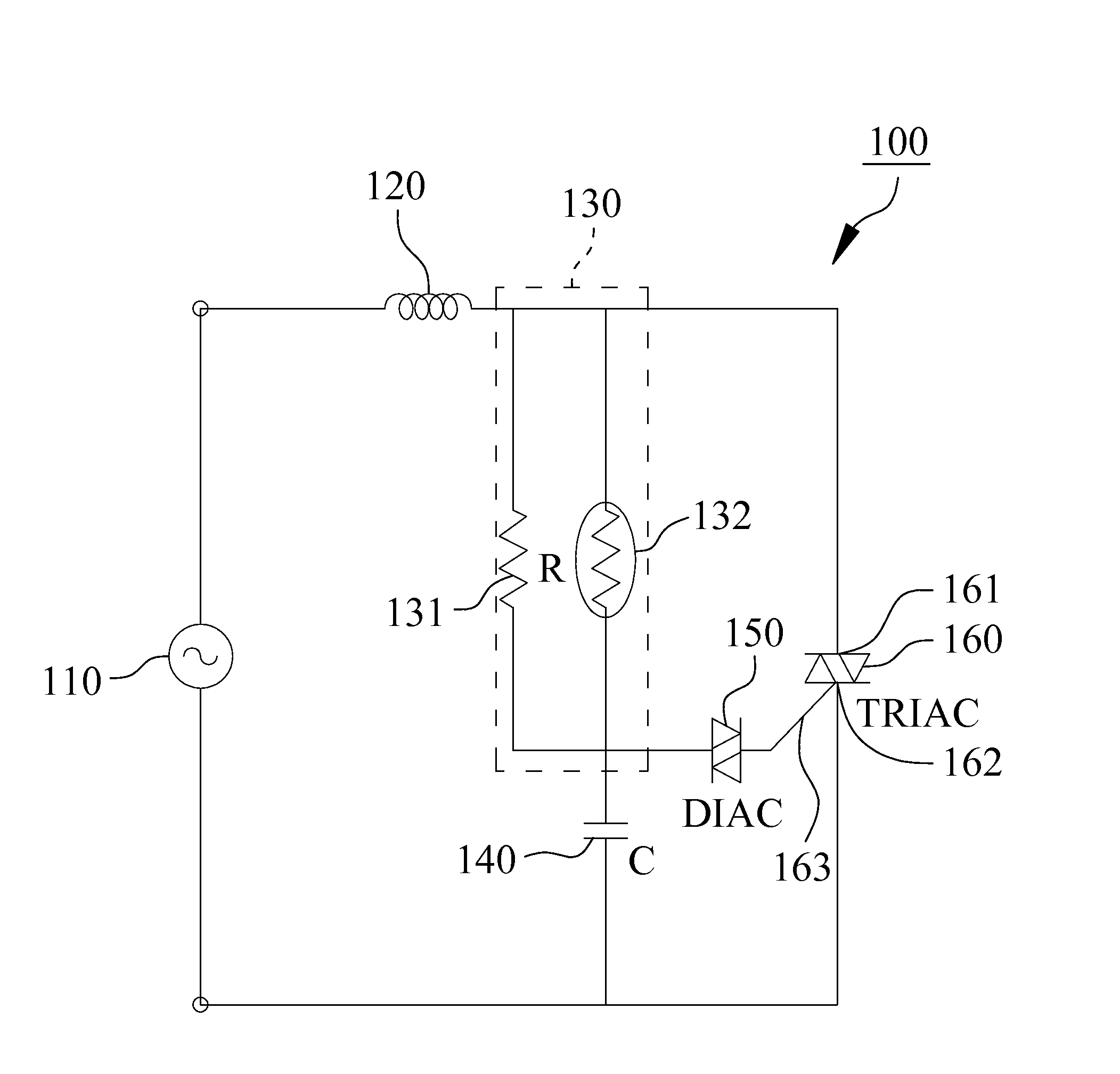
[0003]The primary object of the present invention is to provide a fan rotation speed control circuit comprising an AC power source, a coil, a sensing module, a capacitor, a DIAC and a TRIAC, wherein mentioned coil is electrically connected with the AC power source, and mentioned sensing module is electrically connected with the coil. Mentioned sensing module has a first resistor and a sensing device in parallel connection with the first resistor. The capacitor is electrically connected with the sensing module and in series connection with the sensing module. The DIAC is electrically connected with the sensing module and the capacitor. The TRIAC has a first terminal, a second terminal and a gate terminal, wherein mentioned first terminal is electrically connected with the sensing module and the coil, mentioned second terminal is electrically connected with the capacitor and the AC power source, and mentioned gate terminal is electrically connected with the DIAC. The sensing device may detect the environmental variation (such as temperature environmental variation or light variation) and adjust the fan rotation speed in correspond with different environmental variation. Besides, the fan rotation speed control circuit makes the fan possess capability to achieve maximum rotation speed.

Problems solved by technology

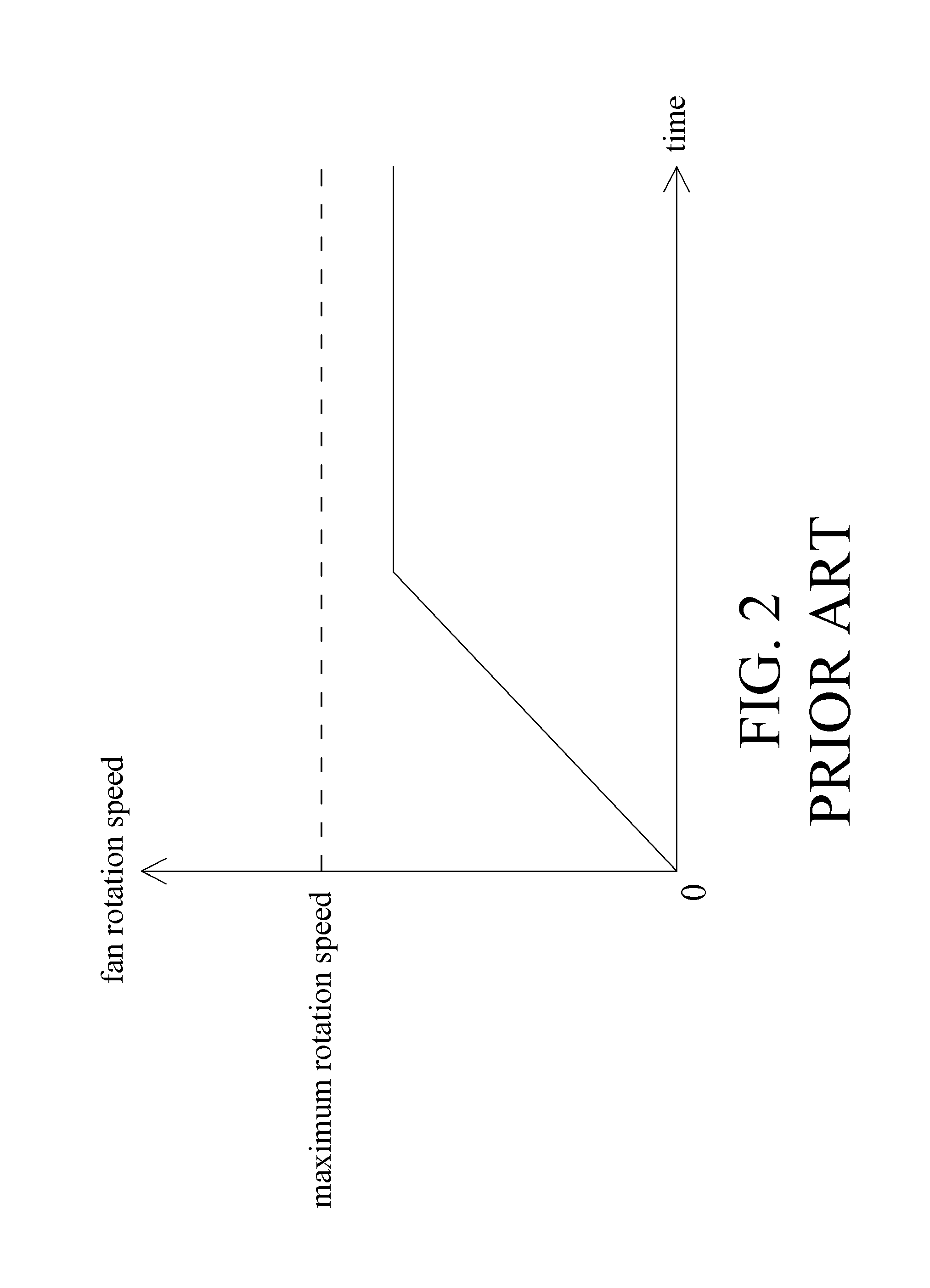
However, the rotation speed of the fan is limited to achieve the maximum rotation speed via restriction of the resistor 230 as illustrated in FIG. 2.

Method used


Image

  • Fan rotation speed control circuit
  • Fan rotation speed control circuit
  • Fan rotation speed control circuit

Examples


Embodiment Construction

[0010]With reference to FIG. 3, a fan rotation speed control circuit 100 in accordance with a first preferred embodiment of the present invention comprises an AC power source 110, a coil 120, a sensing module 130, a capacitor 140, a DIAC (Diode for Alternating Current) 150 and a TRIAC (Triode for Alternating Current) 160, wherein mentioned coil 120 is electrically connected with the AC power source 110, and mentioned sensing module 130 is electrically connected with the coil 120. Mentioned sensing module 130 has a first resistor 131 and a sensing device 132 in parallel connection with the first resistor 131 and is utilized for sensation of environmental variation (environmental temperature variation or light variation) where a fan (not shown in Figure) is situated. In this embodiment, the sensing device 132 can be a temperature sensing device which is chosen from one of positive temperature coefficient thermistor or negative temperature coefficient thermistor, or, the sensing device...


PUM


Abstract

A fan rotation speed control circuit comprises an AC power source, a coil electrically connected with the AC power source, a sensing module having a first resistor and a sensing device in parallel connection with mentioned first resistor, a capacitor, a DIAC, and a TRIAC having a first terminal, a second terminal and a gate terminal, wherein mentioned coil electrically connected with the first resistor and the sensing device, mentioned capacitor electrically connected with the first resistor and the sensing device, mentioned DIAC electrically connected with the first resistor, the sensing device and the capacitor, mentioned first terminal electrically connected with the first resistor, the sensing device and the coil, mentioned second terminal electrically connected with the capacitor and the AC power source, and mentioned gate terminal electrically connected with the DIAC.

Description

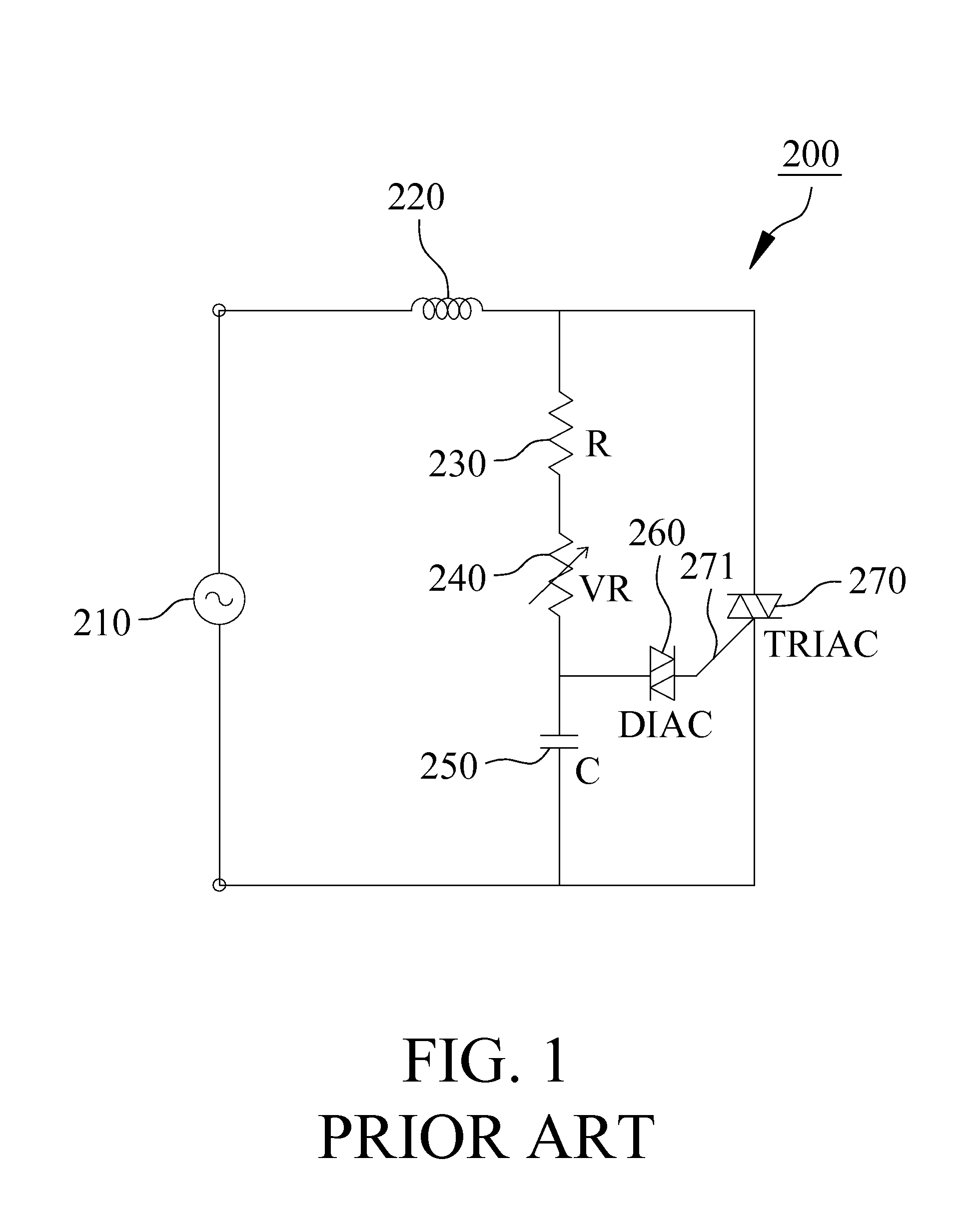
FIELD OF THE INVENTION[0001]The present invention is generally relating to a fan rotation speed control circuit, which particularly illustrates the fan rotation speed control circuit being adaptive to adjust fan rotation speed corresponded to different environmental variation.BACKGROUND OF THE INVENTION[0002]A conventional fan rotation speed control circuit 200 as shown in FIG. 1 comprises an AC power source 210, a coil 220, a resistor 230, a variable resistor 240, a capacitor 250, a DIAC 260 and a TRIAC 270, wherein the coil 220 is electrically connected with the AC power source 210, mentioned coil 220 is electrically connected with the resistor 230 and one end of the TRIAC 270, and another end of the resistor 230 is electrically connected with the variable resistor 240. The capacitor 250 is electrically connected with the variable resistor 240. The resistor 230, the variable resistor 240 and the capacitor 250 are series connected in sequence. One end of the DIAC 260 is electricall...

Claims


Application Information

Patent Timeline
Patent Type & Authority Applications(United States)
IPC IPC(8): H02P23/08H02P25/10H02P23/00
CPCF04D27/004Y02B30/70
Inventor LIN, YU-LIANGLEE, CHUN-HSUEH
Owner ADDA
Why Eureka
Try Eureka