Active differential and motor vehicle

a technology of active differential and motor vehicle, which is applied in the direction of mechanical equipment, transportation and packaging, and transportation of goods, can solve problems such as damage to distributor motors, and achieve the effect of extending the service life of components and reducing electrical loads

Active Publication Date: 2018-04-17
AUDI AG
View PDF17 Cites 1 Cited by
  • Summary
  • Abstract
  • Description
  • Claims
  • Application Information

AI Technical Summary

Benefits of technology

[0006]The invention is thus based on the object of specifying an active differential which makes it possible to reduce the loads of the electrical and mechanical components of the active differential and thus in particular to extend the service life of the components.
[0008]The invention is based on the idea of avoiding damage and high loads of the transmission by which the distributor shaft is separated from the planetary gear train when the operating parameter exceeds certain limit values. The active control of the differential is thus applied and the differential distributes the torque of the drive motor evenly to the output shafts when no additional elements for the complete or partial blocking of the differential are provided. A separation of distributor shaft from the planetary transmission is particularly advantageous since the distributor shaft or the distributor motor is typically operated at high rotational speeds, that is, the planetary gear train or another gear is configured such that the rotational speed of the distributor shaft is higher than the rotational speed difference between the output shafts by a predetermined factor during operation of the active differential. Thus, very high rotational speeds of distributor shaft and thus the distributor motor may thus occur, especially with suddenly occurring large rotational speed differences between the output shafts, which may lead to damage of the distributor motor. This can be avoided by a timely separation of the distributor shaft and thus the distributor motor from the planetary gear train. Also, especially sudden high torque loads to the distributor shaft and thus to the distributor motor can be avoided.
[0010]The operating parameter can be a rotational speed difference between the rotational speeds of the output shafts. The rotational speed of the distributor shaft and thus typically the rotational speed of the distributor motor corresponds to the difference of the rotational speeds between the output shafts scaled with a translation factor. In order to achieve large torque differences between the output shafts through relatively compact distributor motors, the planetary gear train and further gears are typically designed such that the translation factor is relatively large, that is, the distributor shaft has far greater rotational speeds than the difference between the rotational speeds of the output shafts. When the differential is now used, for example, in the motor vehicle and a wheel loses traction, for example, by a lifting the wheel or by a sudden change in friction value, it is thus possible that the rotational speed of this wheel, and thus the output shaft, is greatly increased in the short term as a result of the predetermined torque transmission to the output shafts and in some circumstances by the type of control of the drive motor. In this case, the rotational speed difference between the output shafts and thus the rotational speed of the distributor shaft becomes very large. When a maximum rotational speed of the distributor motor, which for typical electric motors is typically in the range of 10,000 to 15,000 revolutions per minute, is exceeded, damage to the distributor motor may occur after a relatively short time. It is also possible that high currents that must be dissipated are induced in the distributor motor by the great rotational speed. This greatly overloads the power electronics components of the active differential. An intervention by controlling the drive motor and / or the distributor motor can only take place with a relatively large response time since motors have a certain inertia. Therefore, such a control intervention may often not be sufficient to avoid heavy loads of the active differential and a separation of distributor shaft from the planetary gear train by the coupler according to the invention is advantageous.
[0017]As mentioned above, it is advantageously possible that the coupling device itself is mechanically designed such that the distributor shaft is separated from the planetary gear train when an operating parameter of the differential exceeds a predefined limit value, so that a control device is not necessarily needed for the construction of an active differential according to the invention. This can be achieved when the coupling device is a slip clutch or includes a slip clutch. The slip clutch thereby separates the distributor shaft from the planetary gear train upon application of a defined torque. The torque applied to a coupling device that is arranged between distributor shaft and planetary gear train is proportional to the output torque difference. Thus, the use of a slip clutch is particularly advantageous when the operating parameter is the output torque difference.

Problems solved by technology

Thus, very high rotational speeds of distributor shaft and thus the distributor motor may thus occur, especially with suddenly occurring large rotational speed differences between the output shafts, which may lead to damage of the distributor motor.

Method used


Image

  • Active differential and motor vehicle
  • Active differential and motor vehicle

Examples


Embodiment Construction

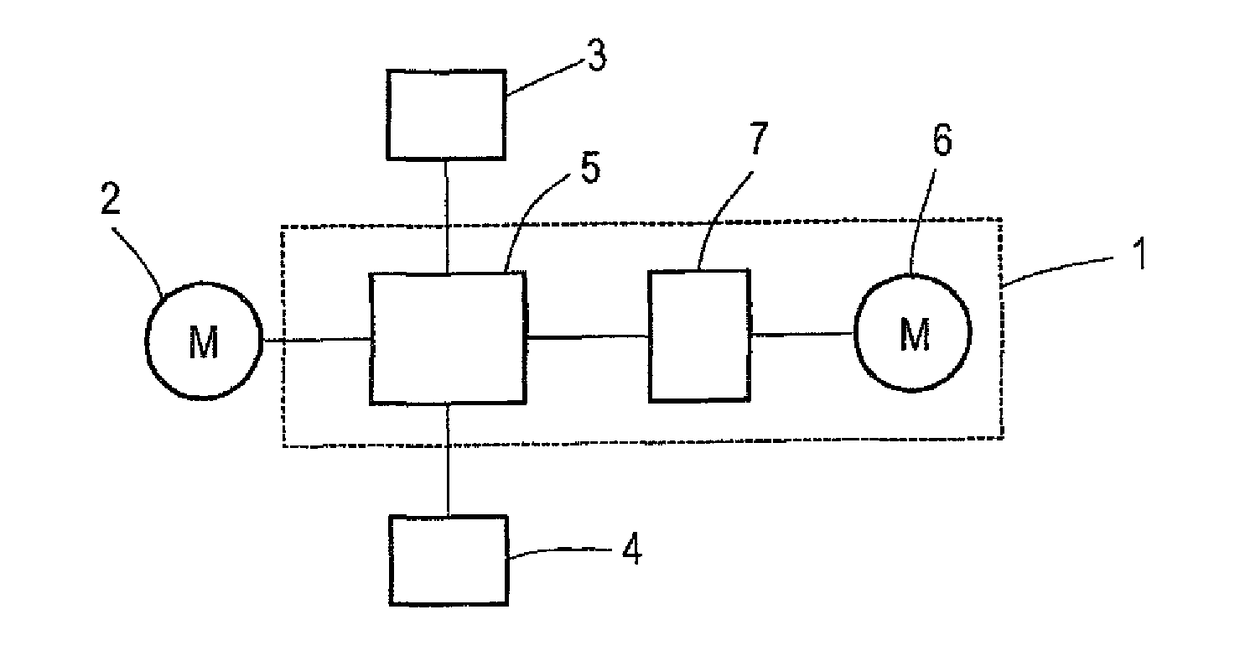
[0029]FIG. 1 shows an embodiment of an active differential 1 for the controlled distribution of a drive torque generated by a drive motor 2 to two output shafts 3, 4. The coupling of the drive motor 2 and the output shaft to the output shafts 3, 4 takes place through the planetary gear train 5 of the differential 1. In addition to the planetary gear train 5, the differential 1 includes a distributor motor 6, wherein the distribution of drive torque to the output shafts 3, 4 depends on the torque exerted by the distributor motor 6. The distributor motor 6 is coupled via a distributor shaft to the coupling device 7, which in turn is coupled to the planetary gear train 5. When the coupling device 7 separates the distributor shaft coming from the distributor motor 6 from the planetary gear train 5, the differential 1 the behavior of a non-locked differential, so that the torque generated by the drive motor 2 is equally distributed to the output shafts 3 and 4. When the distributor shaft...


PUM


Abstract

An active differential for the controlled distribution of a drive torque generated by a drive motor to two output shafts includes a planetary gear train configured to couple the two drive shafts to a drive shaft of the drive motor, and a distributor motor including a distributor shaft. The distributor motor produces a torque, with a distribution of a drive torque to the two output shafts being dependent on the torque produced by the distributor motor. The distributor shaft and the planetary gear train are coupled by a coupling device which is configured to separate the distributor shaft from the planetary gear train when an operating parameter of the active differential exceeds a predetermined limit value. The operating parameter can hereby be an output torque difference between torques transmitted from the output shafts to the planetary gear train or a time derivative of the output torque difference.

Description

CROSS-REFERENCES TO RELATED APPLICATIONS[0001]This application is the U.S. National Stage of International Application No. PCT / EP2014 / 003019, filed Nov. 11, 2014, which designated the United States and has been published as International Publication No. WO 2015 / 0785558 and which claims the priority of German Patent Application, Serial No. 10 2013 019 907.7, filed Nov. 28, 2013, pursuant to 35 U.S.C. 119(a)-(d).BACKGROUND OF THE INVENTION[0002]The invention relates to an active differential for the controlled distribution of a drive torque generated by a drive motor to two output shafts, including a planetary gear train for coupling the output shafts to a drive shaft of the drive motor and a distributor shaft to a distributor motor, wherein the distribution of drive torque to the output shafts depends on a torque exerted by the distributor motor.[0003]Active differentials are used to distribute drive torques to a plurality of, in particular two, drive shafts. The differential thus al...

Claims


Application Information

Patent Timeline
Patent Type & Authority Patents(United States)
IPC IPC(8): B60K6/365F16H48/36B60K17/16
CPCF16H48/36B60K17/16F16H2048/364
Inventor PINSCHMIDT, UDOSCHELS, THOMASWOLF, MAXIMILIAN
Owner AUDI AG
Why Eureka
Try Eureka