Automotive cable holding system

a technology for holding systems and automobiles, applied in vehicle components, multi-purpose tools, electric/fluid circuits, etc., can solve the problems of easy increase of mounting man hours and difficulty in fastening work using pins, and achieve the effect of preventing the dislodgement of the bracket from the vehicle body and preventing the dislodgement of the bracket more effectively

Active Publication Date: 2007-03-01
HONDA MOTOR CO LTD
View PDF7 Cites 10 Cited by
  • Summary
  • Abstract
  • Description
  • Claims
  • Application Information

AI Technical Summary

Benefits of technology

[0028] According to the first and second aspects of the invention, the bracket can be mounted on the vehicle body simply by inserting the bracket into the insertion opening, whereby the cable can easily be held on to the vehicle body. In addition, a force with which the cable is pulled can be borne by the abutment of the inner circumferential surface of the insertion opening in the vehicle body with the abutment surface of the bracket. Hence, the engagement of the clip portion with the vehicle body is never released which would otherwise be caused when the force with which the cable is pulled is inputted int

Problems solved by technology

When attempting to mount the manipulator unit on a lower side of a rear parcel shelf, for example, the fastening work using pins was difficult.
In addition, the manipulator u

Method used


Image

  • Automotive cable holding system
  • Automotive cable holding system
  • Automotive cable holding system

Examples


Embodiment Construction

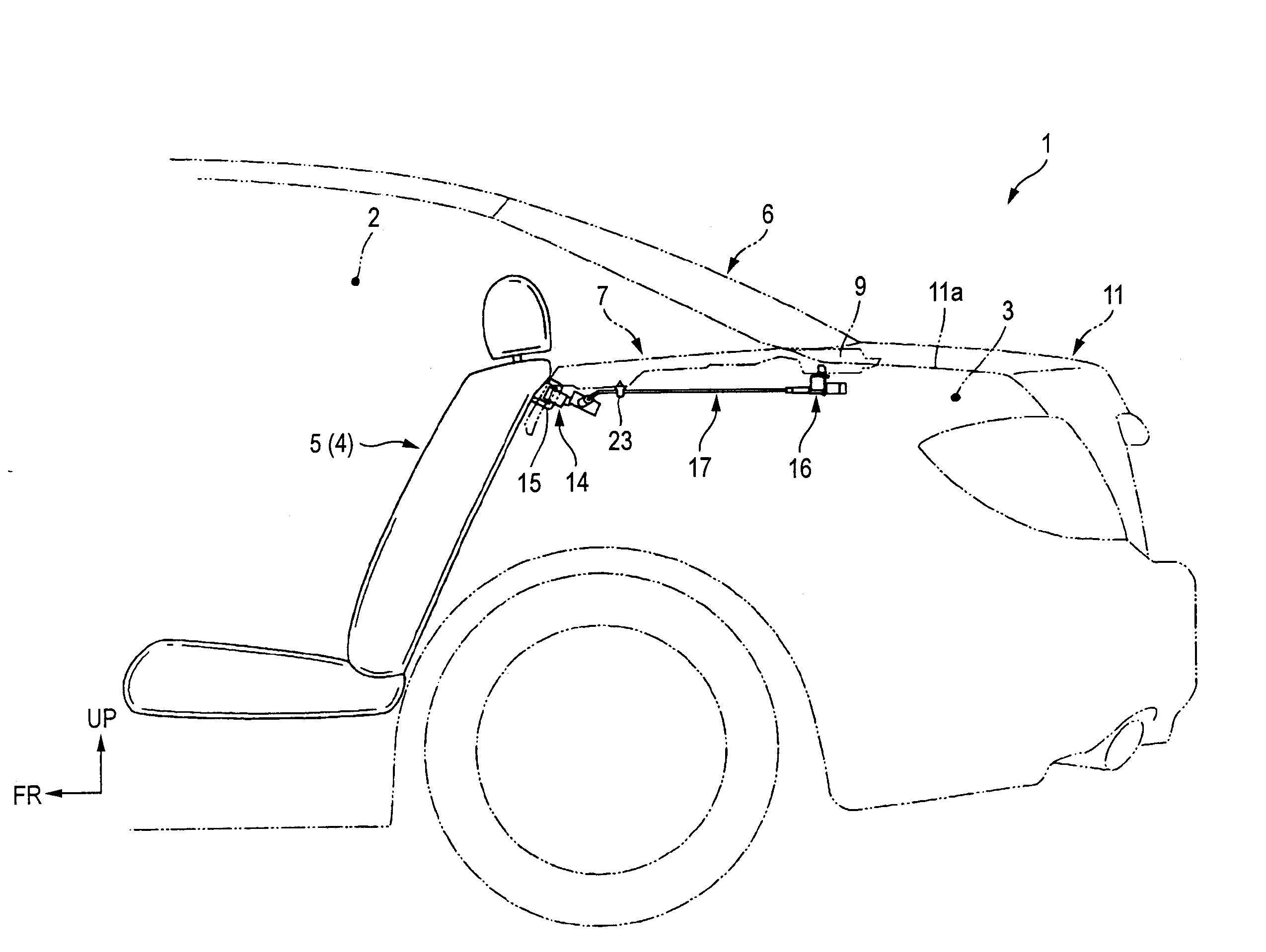
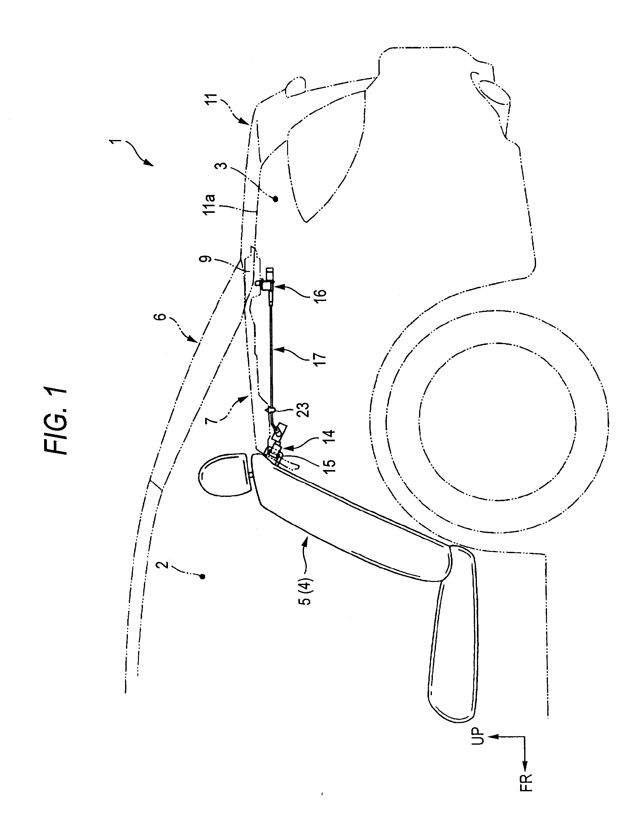
[0036] Hereinafter, an embodiment of the invention will be described by reference to the accompanying drawings. Note that when used in the following description, directions or orientations indicated as front, rear, left, right and the like are understood to coincide with those on the vehicle provided. In addition, in the figures, an arrow indicated as FR indicates the front of the vehicle, an arrow indicated as LH indicates the left-hand side of the vehicle, and an arrow indicated as UP indicates an upward direction of the vehicle.

[0037]FIG. 1 is an explanatory diagram showing a rear part of a vehicle body of a three-box or sedan-type motor vehicle (vehicle) 1, and as shown in the figure, a passenger compartment 2 and a trunk (luggage compartment) 3 which lies at the rear of the passenger compartment 2 are divided by a rear seat backrest 5 of a rear seat 4 lying inside the passenger compartment 2 and a substantially horizontal rear parcel shelf 7 along and between an upper edge por...


PUM


Abstract

The present invention relates to an automotive cable holding system for securing a vehicle body to a cable which is connected at one end to a locking mechanism for a rear seat backrest and at the other end to a releasing mechanism. The automotive cable holding system includes a bracket for holding an end of the cable and an insertion opening in the vehicle body into which the bracket is inserted, wherein the bracket has provided thereon abutment surfaces which abut the inner circumferential surfaces of the insertion opening, an engagement portion extending further outwards than the abutment surfaces at a position lying further inwards than the insertion opening inside the vehicle body and a clip portion disposed on the opposite side to the engagement portion inside the vehicle body.

Description

[0001] This application claims priority under 35 USC 119 from Japanese Patent Application No. 2005-251749, the disclosure of which is herein incorporated by reference. BACKGROUND [0002] 1. Technical Field [0003] The present invention relates to an automotive cable holding system for holding a cable of a vehicle on to a vehicle body, and more particularly to an automotive cable holding system for holding a cable provided between a locking mechanism for a backrest of a rear seat and a manipulator unit for manipulating the locking mechanism to release the locking by the locking mechanism. [0004] 2. Related Art [0005] As a conventional cable holding system, there is known a cable holding system in which a manipulator unit provided at one end portion of a cable is mounted on a vehicle body by pins (for example, see JP-A-10-86716). [0006] In the cable holding system referred to above, however, the positioning of the manipulator unit relative to the vehicle body becomes necessary when moun...

Claims


Application Information

Patent Timeline
IPC IPC(8): H02G3/06
CPCB60R16/0215H02G3/32Y10T16/05Y10T16/063
Inventor SHIMADU, MASAKI
Owner HONDA MOTOR CO LTD
Why Eureka
Try Eureka