Collision detecting system
- Summary
- Abstract
- Description
- Claims
- Application Information
AI Technical Summary
Benefits of technology
Problems solved by technology
Method used
Image

Examples
first embodiment
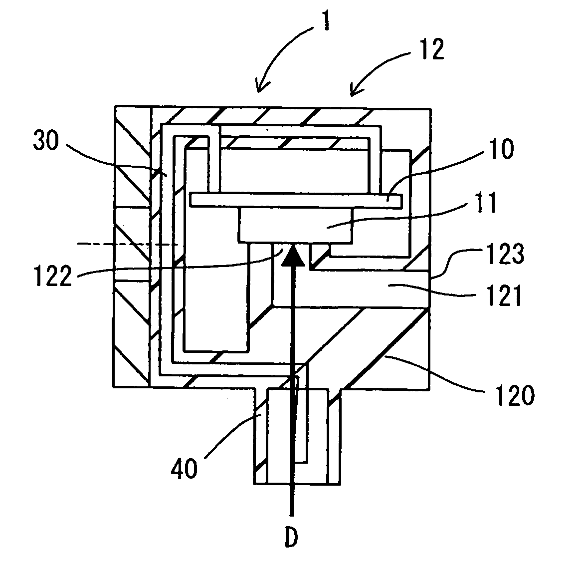
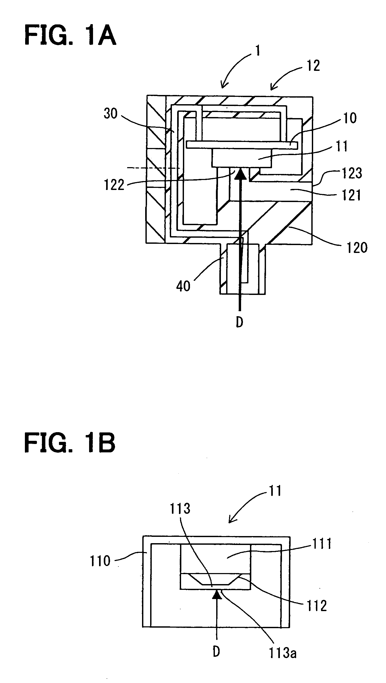
[0025] A collision detecting system according to a first embodiment of the present invention will be described with reference to FIGS. 1A-4. The collision detecting system can be suitably used for a vehicle, for example.
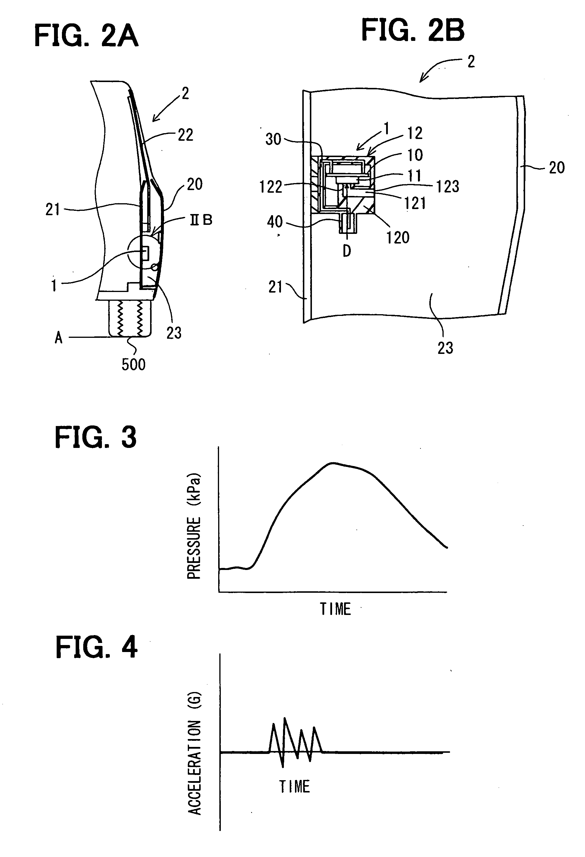
[0026] Referring to FIGS. 2A and 2B, the collision detecting system has a pressure detecting device 1 for detecting an inner pressure of a door 2 (i.e., pressure in space 23 of interior of door 2) of the vehicle. The door 2 has an outer panel 20, an inner panel 21 and a window glass 22. The outer panel 20 constructs a part of an exterior member of the vehicle. The inner panel 21 constructs a part of an interior member of the vehicle. That is, the inner panel 21 is positioned at the side of a passenger compartment of the vehicle.
[0027] The door 2 has therein a substantially closed space 23 between the outer panel 20 and the inner panel 21. The space 23 has a small communication (fluid communication) with the exterior of the door 2. When the pressure (air pressure) o...
second embodiment
[0054] According to a second embodiment of the present invention with reference to FIG. 5, the pressure detecting member 11 of the pressure detecting device 1 is mounted in such a manner that the detection direction D of the pressure detecting member 11 is substantially parallel to the surface of the circuit board 10.
[0055] That is, the relative position between the pressure detecting member 11 and the circuit board 10 is different from that in the first embodiment, where the detection direction D of the pressure detecting member 11 is substantially perpendicular to the surface of the circuit board 10.
[0056] About the collision detecting system, what has not been described in the second embodiment is the same with the first embodiment. The collision detecting system according to the second embodiment has the same effect with that according to the first embodiment.
[0057] A conventional collision detecting system will be described with reference to FIGS. 6-8, as a comparison exampl...
third embodiment
[0062] A third embodiment of the present invention will be described with reference to FIGS. 9A and 9B.
[0063] In this case, the pressure detecting device 1 is attached to a substantially L-shaped stay 3 which is fixed to the inner panel 21 of the door 2. That is, the stay 3 has two portions which are substantially perpendicular to each other and respectively fixed to the inner panel 21 of the door 2 and the vehicle mounting side of the pressure detecting device 1, so that the detection direction D of the pressure detecting device 1 is in the substantially vertical direction.
[0064] According to this embodiment, the detection direction D of the pressure detecting device 1 is in the substantially vertical direction which is perpendicular to the direction of the impact load applied to the vehicle due to the collision. Thus, the vehicle vibration excited by the impact load from the collision is hardly detected by the pressure detecting device 1. Therefore, the collision detecting syste...
PUM
 Abstract
Description
Claims
Application Information
 - Generate Ideas
- Intellectual Property
- Life Sciences
- Materials
- Tech Scout
- Unparalleled Data Quality
- Higher Quality Content
- 60% Fewer Hallucinations
Browse by: Latest US Patents, China's latest patents, Technical Efficacy Thesaurus, Application Domain, Technology Topic, Popular Technical Reports.
© 2025 PatSnap. All rights reserved.Legal|Privacy policy|Modern Slavery Act Transparency Statement|Sitemap|About US| Contact US: help@patsnap.com