Scaffold frame section with integral guard rail post

a guard rail and scaffold frame technology, applied in the direction of scaffold accessories, constructions, building aids, etc., can solve the problems of unsafe elevated positions of platforms, scaffold assemblies with improperly and unsafe positions, and significant falling hazards for workers standing on platforms

Inactive Publication Date: 2007-03-01
WYSE STEVEN
View PDF11 Cites 34 Cited by
  • Summary
  • Abstract
  • Description
  • Claims
  • Application Information

AI Technical Summary

Benefits of technology

[0009] The present invention overcomes the problems outlined above, and provides a scaffold assembly including a pair of end frames, each comprising a pair of laterally spaced apart, upright standards having opposed upper and lower ends, with a primary platform ledger extending between and interconnected with the standards. Each primary ledger is located a safety distance of at least about thirty (30) inches (more preferably from about thirty-six (36) to forty-two (42) inches) below the upper end of the corresponding standard. One or more personnel platforms span and are operatively supported by the end frame ledgers. Additionally, the end frames are free of platform ledgers within the safety distance above the primary ledger, so that no platform may be installed above the primary ledgers. In order to erect a free-standing scaffold, cross-tie structure is employed to interconnect the end frames. Finally, the overall scaffold assembly has a guardrail assembly extending between the end frames in the safety distance above the personnel platform.
[0010] The scaffold assemblies of the invention may be provided in stacked relati...

Problems solved by technology

As can be appreciated, if a personnel platform is located near the very top of a scaffolding unit, workers standing on the platforms may be subjected to significant falling hazard owing to the fact that inadequate guardrails are present.
While these safety standards have been in place for several years, it is still possible with existing scaffold designs to inadvertently or intentionally construct a scaffold assembly with improperly and unsafely positioned personnel platforms.
In such a case, those constructing the scaffolding, either from exped...

Method used


Image

  • Scaffold frame section with integral guard rail post
  • Scaffold frame section with integral guard rail post
  • Scaffold frame section with integral guard rail post

Examples


Embodiment Construction

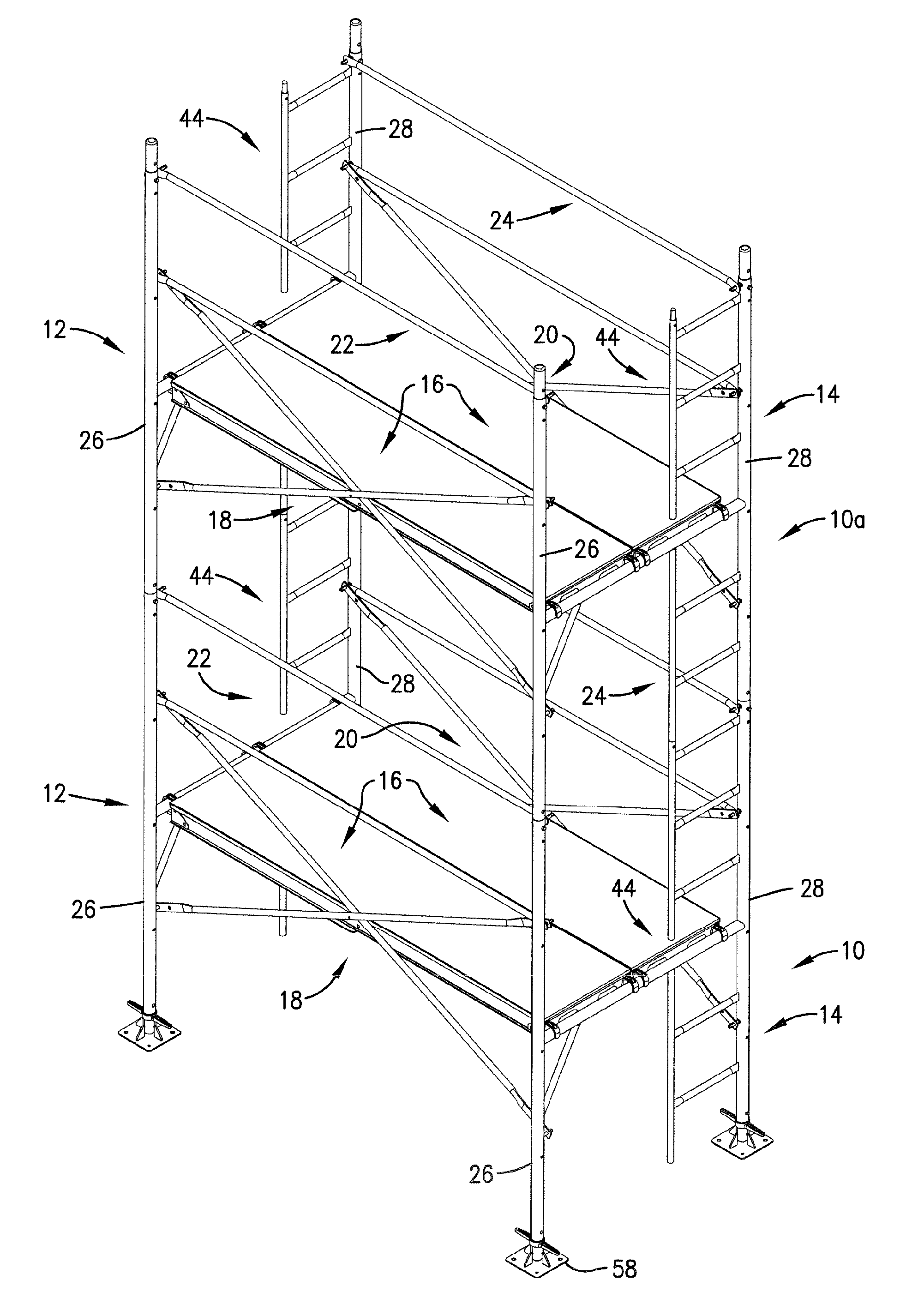
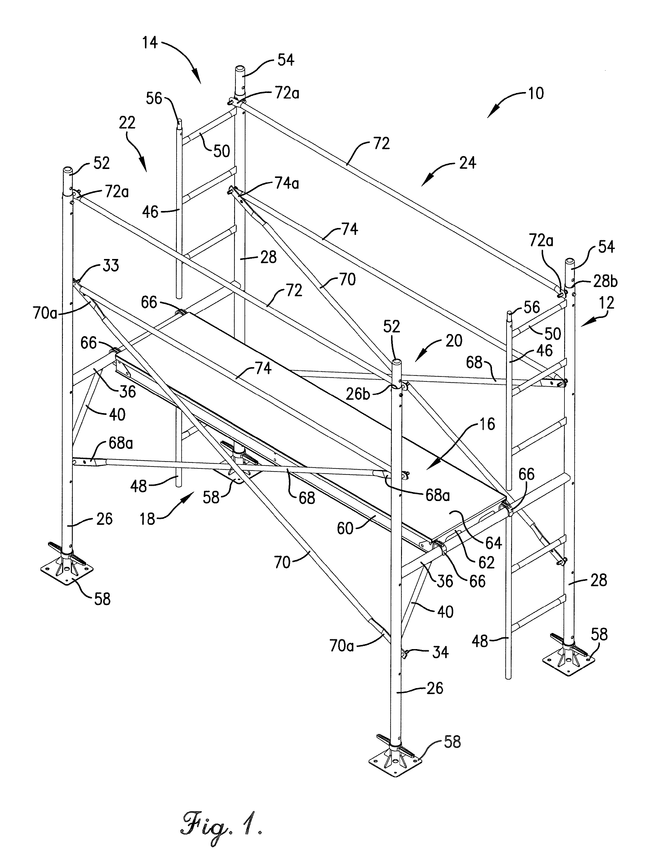
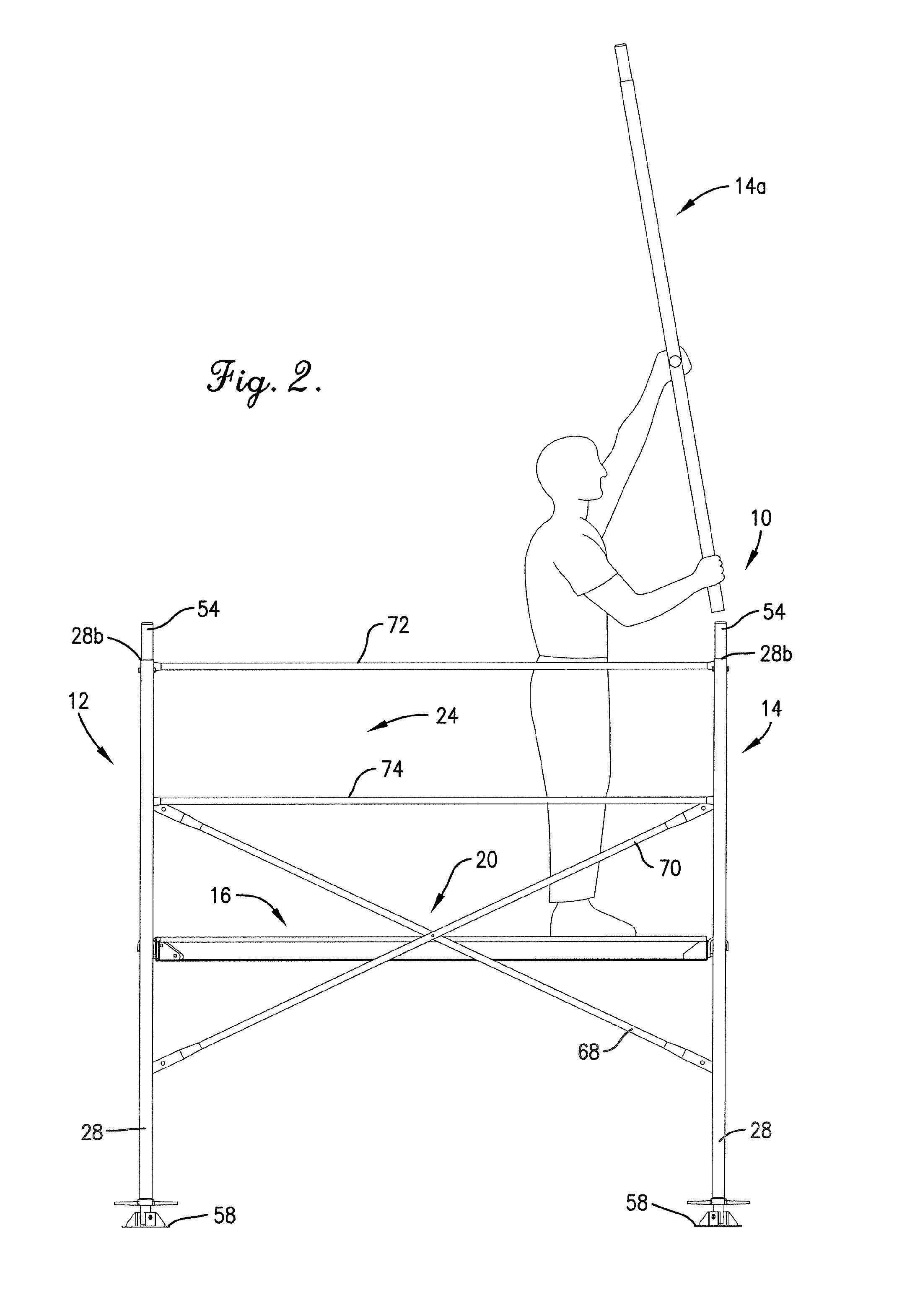
[0024] Turning now to the drawings, the scaffold assembly 10 selected for illustration in FIG. 1 broadly includes a pair of preconstructed end frames 12,14, a personnel platform 16, cross-tie assemblies 18,20, and guardrail assemblies 22,24. As shown, the assembly 10 is a free-standing unit for use on construction sites or in similar contexts.

[0025] In more detail, the end frames 12,14 in the depicted embodiment are mirror images of each other. Thus, only the end frame 12 will be described in detail, with the understanding that the other end frame 14 is similarly constructed. Furthermore, the same reference numerals will be used to identify similar components of the end frame 12 and 14.

[0026] As perhaps best shown in FIG. 4, the end frame 12 preferably includes a pair of upright standards 26,28, each having lower ends 26a,28a and upper ends 26b,28b. In the preferred embodiment, the standards are formed of metal (e.g., steel or Aluminum) and have a circular, tubular configuration, ...


PUM


Abstract

An enhanced safety scaffold assembly (10) is provided including end frames (12,14) interconnected by means of cross-tie structure (18,20). The end frames (12,14) include ledgers (36) located a safety distance (38) of at least about thirty inches below the upper ends (26b,28b) of the standards (26,28), and are free of additional ledgers within the safety distance. A platform (16) is supported by the ledgers (36), and guardrail assemblies (22,24) extend between opposed standards (26,28). In this way, the platform (16) is located well below the upper ends (26b,28b) of the standards (26,28) in accordance with existing safety regulations, and placement of a platform (16) in an unsafe, elevated position is precluded. The assemblies of the invention may be constructed in a variety of ways to include optional leveling units (58), ladders (44), outriggers (134) and supplemental work platforms (144).

Description

CROSS REFERENCE TO RELATED APPLICATION [0001] This application is being filed contemporaneously with application for U.S. Design patent Ser. No. ______, entitled SCAFFOLD FRAME SECTION WITH INTEGRAL GUARD RAIL POST, which is hereby incorporated by reference herein. BACKGROUND OF THE INVENTION [0002] 1. Field of the Invention [0003] The present invention is broadly concerned with improved scaffold assemblies and components thereof which are designed for enhanced user safety. More particularly, the invention is concerned with scaffold assemblies and the end frames forming a part thereof, wherein personnel platform-supporting ledgers are provided at a significant safety distance below the upper ends of the platform end frames so that a user is precluded from positioning a personnel platform at an elevated, unsafe position. [0004] 2. Description of the Prior Art [0005] Scaffolding of various types has been provided in myriad forms over the years. To be effective, construction site scaff...

Claims


Application Information

Patent Timeline
IPC IPC(8): E04G7/00
CPCE04G1/14E04G1/24E04G5/06E04G2001/248E04G5/14E04G5/061E04G5/10
Inventor WYSE, STEVEN
Owner WYSE STEVEN
Why Eureka
Try Eureka