Setting tool

Active Publication Date: 2007-03-01
HILTI AG
View PDF13 Cites 1 Cited by
  • Summary
  • Abstract
  • Description
  • Claims
  • Application Information

AI Technical Summary

Benefits of technology

[0013] Addition of the inertia body leads to a new mass distribution. As a result of mass distribution, at the first contact between the setting piston and the stop element, it is not the inertia force of the total mass of the stop element and the inertia body that acts as a counter-force on the setting piston for braking the setting piston. Rather, only a portion of the inertia force ascribed to the mass of the stop element acts on the setting piston. Thereby, the force peak, which appears on an impact, is reduced, and the setting piston is less loaded. Further, the multi-stage braking of the setting piston is achieved with a smaller resilient deflection, which positively influences the service life of the setting piston and the bolt guide. Still further, the stop element, upon rebound of the damping element, shortly after its change of direction, is displaced away from the inertia body in a direction opposite the setting direction, while the inertia body, because of its mass moment of inertia continues to displace in the setting direction within limits of the decoupling path. This displacement is stopped when the inertia body contacts the second stop. This leads to a low, non-critical rebound speed of the setting piston.
[0014] Advantageously, the inertia body is ring-shaped at least regionwise and is displaceable along a circumferential track provided on the stop element. Thereby, tilting and an outside function of the inertia body is prevented. Alternatively, the track can be provided on the piston guide.
[0016] According to an advantageous embodiment of the present invention, the inertia body is formed as an elongate body projecting beyond the stop element in a direction opposite the bolt guide and has a collar embracing the stop element. This formation of the inertia body further increases its mass, which further reduces the rebound speed of the setting piston.

Problems solved by technology

This leads to a low, non-critical rebound speed of the setting piston.

Method used


Image

  • Setting tool
  • Setting tool
  • Setting tool

Examples


Embodiment Construction

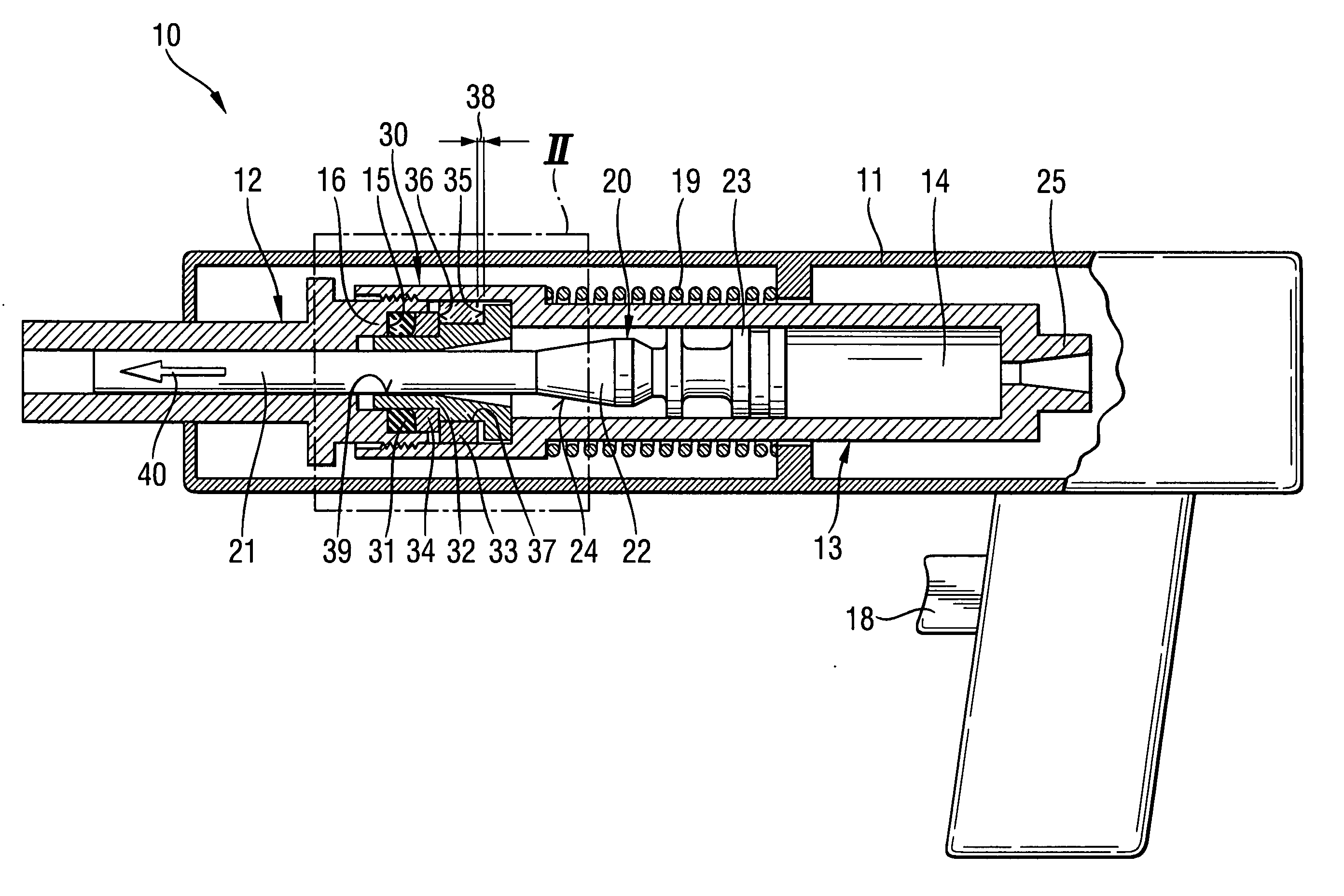
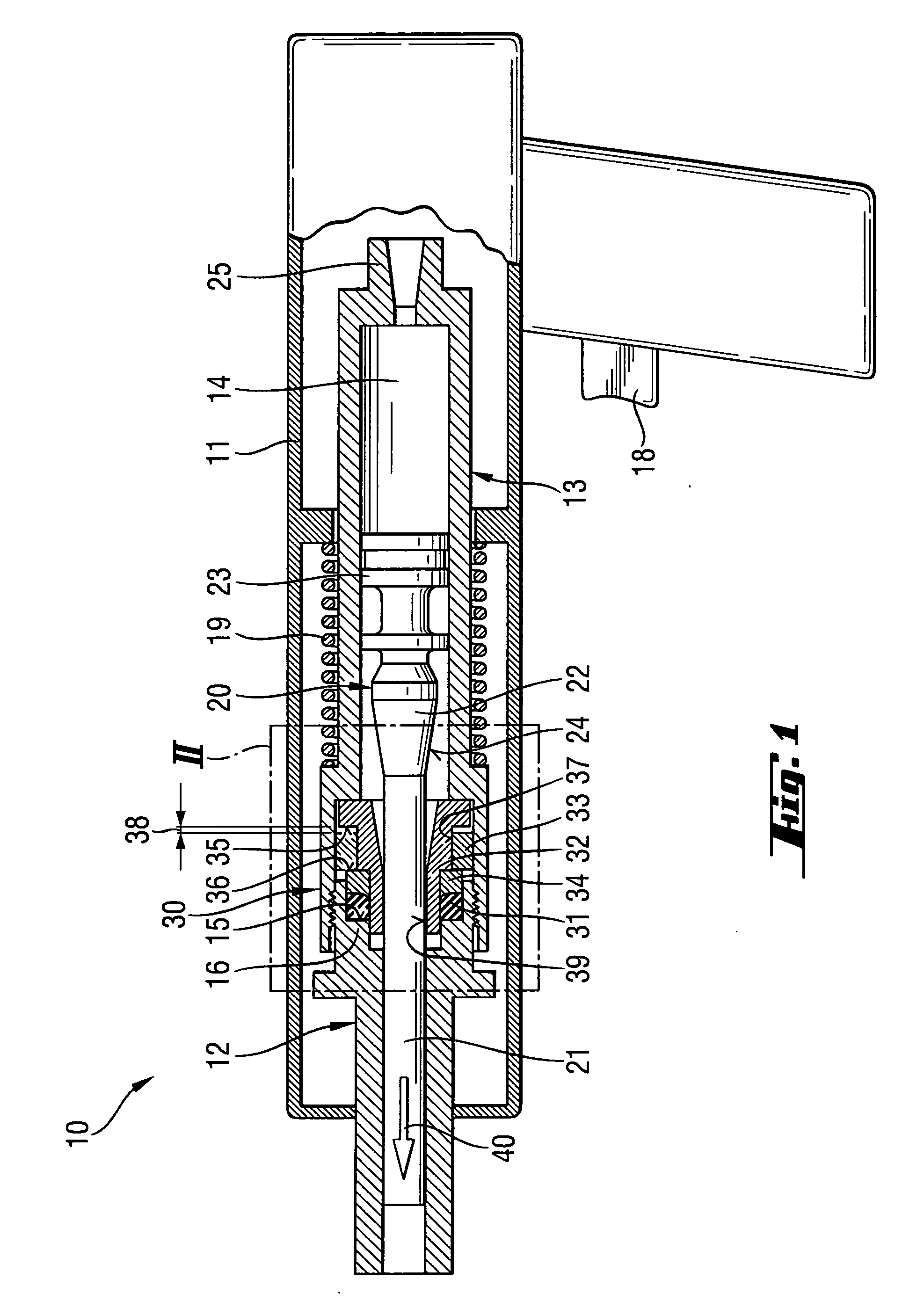
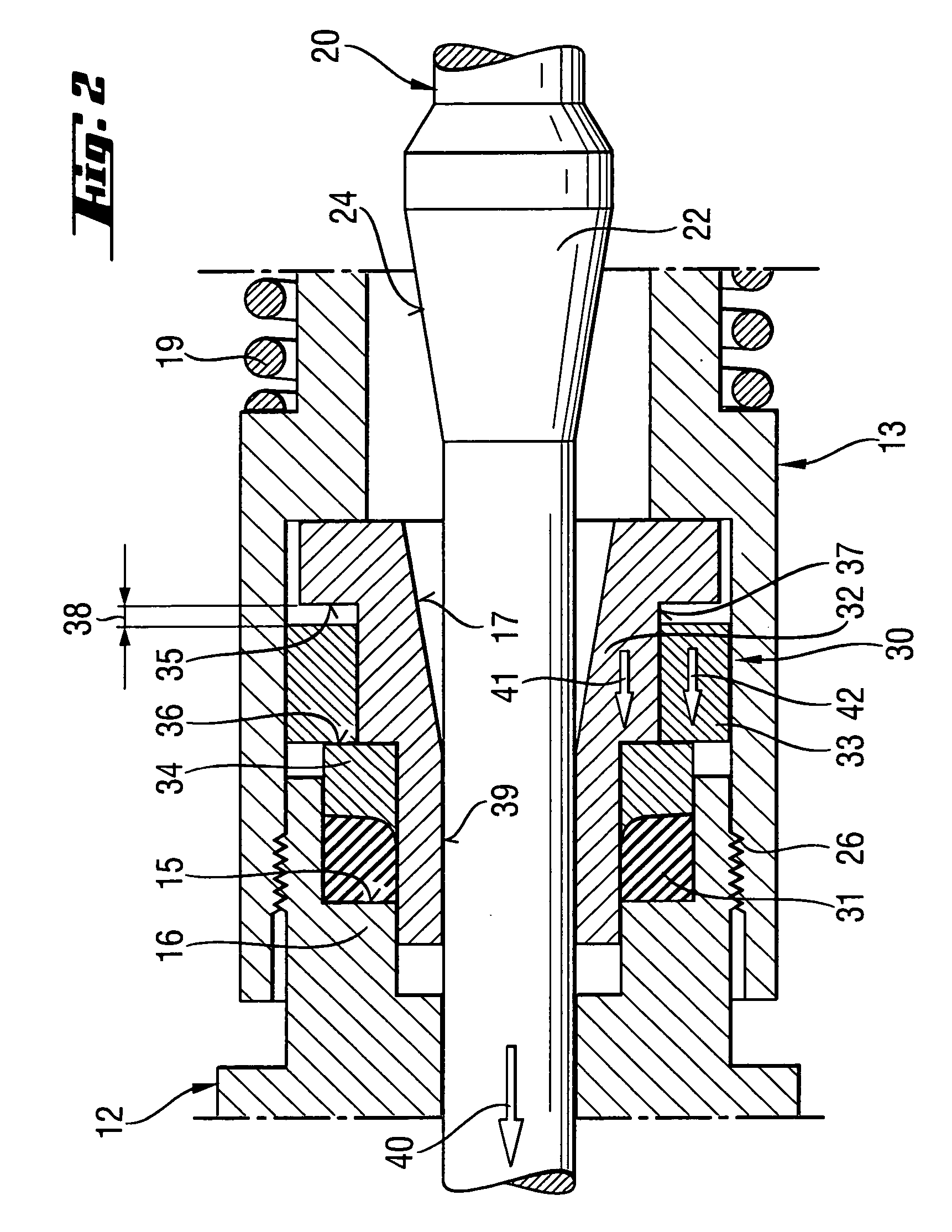
[0022] A setting tool 10 according to the present invention, which is shown in FIGS. 1-2, has a piston stop device generally designated with a reference numeral 30. The setting tool 10 further includes a one- or multi-piece housing 11 and a piston guide 13 arranged in the housing 11. In the hollow chamber 14 of the piston guide 13, a setting piston 20 is displaceably arranged. The setting piston 20 is driven by a propellant or its reaction products, e.g., combustion gases or the like. The setting piston 20 has a piston stem 21 that adjoins, in a setting direction 40 of the setting tool 10, a piston head 23. On a piston stem 21, there is provided a piston collar 22 in a spaced relationship to the piston head 23. The piston collar 22 has a counter-stop surface 24 facing in a direction of the piston stop device. The counter-stop surface 24 is formed, in the embodiment shown in FIGS. 1-2, as a conical surface. The piston collar 22 can be arranged differently than shown in the drawings b...


PUM

PropertyMeasurementUnit
Lengthaaaaaaaaaa
Lengthaaaaaaaaaa

Abstract

A setting tool for driving fastening elements in a constructional component includes piston stop device (30) for braking the setting piston (20) and which is located at an end region of the hollow chamber (14) of the piston guide (13) in which the setting piston is displaceable, adjacent to the bolt guide (12), and has a damping element (31) supported against a bottom (15), a stop element (32) for the setting piston (20) and adjoining the damping element (31) in a direction of the hollow chamber (14), and an inertia body (33) cooperating with the stop element (32) and displaceable in a direction parallel to a longitudinal extent of the setting piston (20) between a first stop (35) and a second stop (36) both of which are connected with the stop element (32) and a distance between which, in a direction parallel to the longitudinal extent of the setting piston (20), is greater than a length of the inertia body (33) in a same direction by length of a decoupling path (38).

Description

BACKGROUND OF THE INVENTION [0001] 1. Field of the Invention [0002] The present invention relates to a setting tool for driving fastening elements in a constructional component and including a piston guide having a hollow chamber, a setting piston axially displaceable in the hollow chamber and having a piston head and a piston stem adjoining the piston head, a bolt guide adjoining the piston guide in a setting direction of the setting tool, and a piston stop device for braking the setting piston, located at an end region of the hollow chamber adjacent to the bolt guide, the piston stop device having a damping element supported against a bottom and a stop element for the setting piston and adjoining the damping element in a direction of the hollow chamber. [0003] 2. Description of the Prior Art [0004] Setting tools of the type described above can be operated with solid, gaseous, or fluid fuels or with compressed air. With combustion-operated setting tool, the setting piston is driven...

Claims


Application Information

Patent Timeline
IPC IPC(8): B25C1/14
CPCB25C1/14
Inventor SPERRFECHTER, THOMASHAHN, WOLFRAM
Owner HILTI AG
Why Eureka
Try Eureka