Wheeled can for bar refuse

a technology for bar refuse and cans, applied in the field of wheeled cans, can solve the problems of increasing the cost of molds, designing containers, and large volume of refuse containers

Inactive Publication Date: 2007-03-01
YOUNG ROGER L
View PDF16 Cites 13 Cited by
  • Summary
  • Abstract
  • Description
  • Claims
  • Application Information

AI Technical Summary

Benefits of technology

[0008] Generally, the present invention provides a wheeled can that accepts bar refuse and the wheels fit within the footprint of the can. The can has a generally hollow body with an open top and a closed bottom. The top has a width and a depth to fit within a narrow and limited depth opening at the end of a bar. Near the top, the can has two reinforcing ribs integral to the body. At least one handle extends from a lower rib on the width or lateral side of the can. The can tapers downwards for its length on both the width and the depth of the body. The bottom is generally narrower in width and depth than the top. Proximate to the bottom, two corners of the body are recessed inwards and curved to accept a wheel. The corners are shaped to include a slot that accepts an axle. In use, the wheels are placed at the ends of the axle and then the axle is pressed into the slot with the wheels turning upon the axle and within the recess. The wheels fit within the width and depth at the bottom and established by the tapering of the sides, front, and back of the container. Fitting within those dimensions, the wheels allow staff at a bar to remove the can from a confined space readily.

Problems solved by technology

Refuse containers generally have a large volume but light weight.
The difficulty in designing a container for nesting and a small space is shown by the operation of a typical device, particularly that device of the inventor now U.S. Pat. No. 6,769,702.
The mold thus has more recesses and intricacies raising the cost of the mold.

Method used


Image

  • Wheeled can for bar refuse
  • Wheeled can for bar refuse
  • Wheeled can for bar refuse

Examples


Embodiment Construction

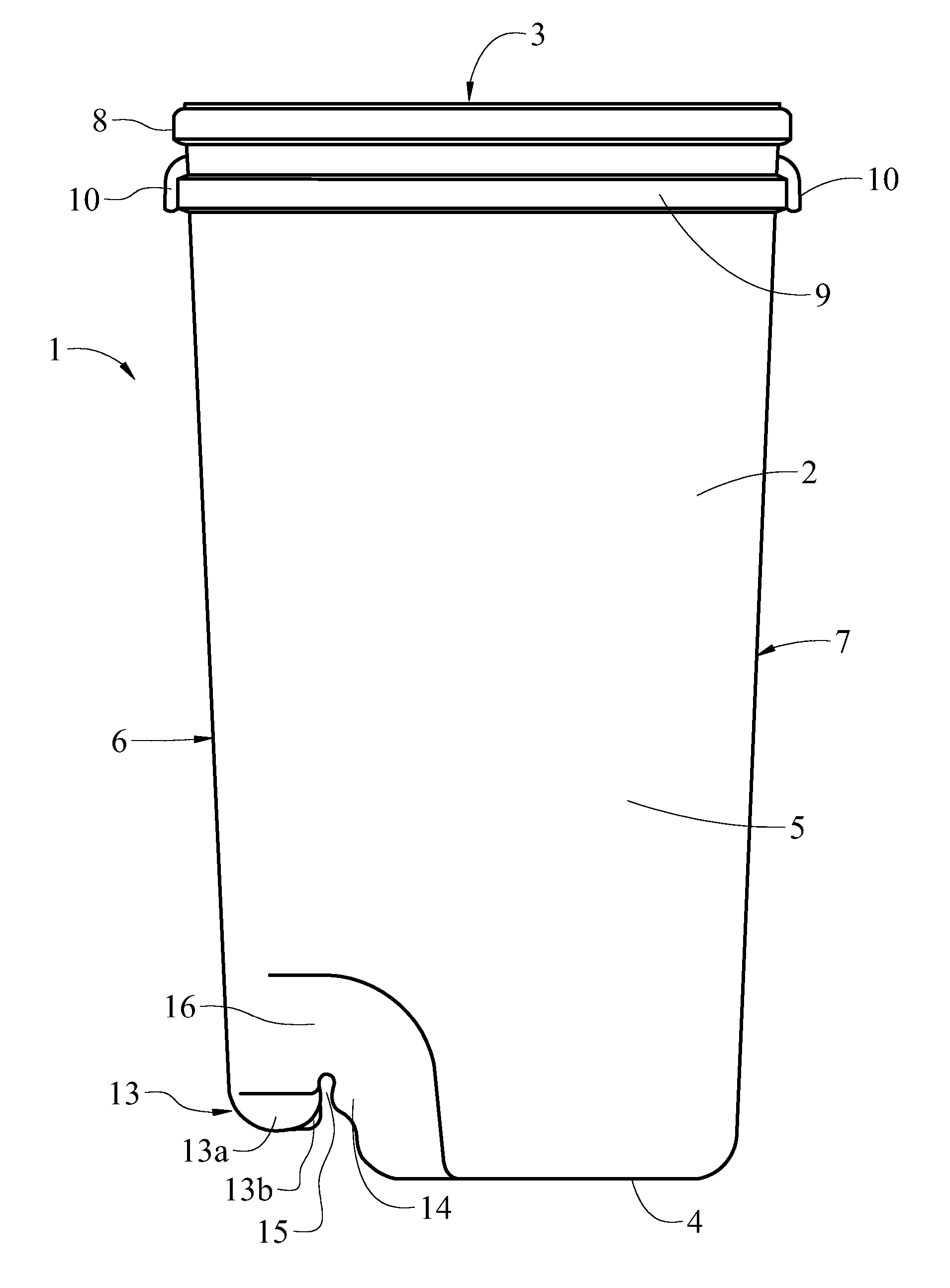
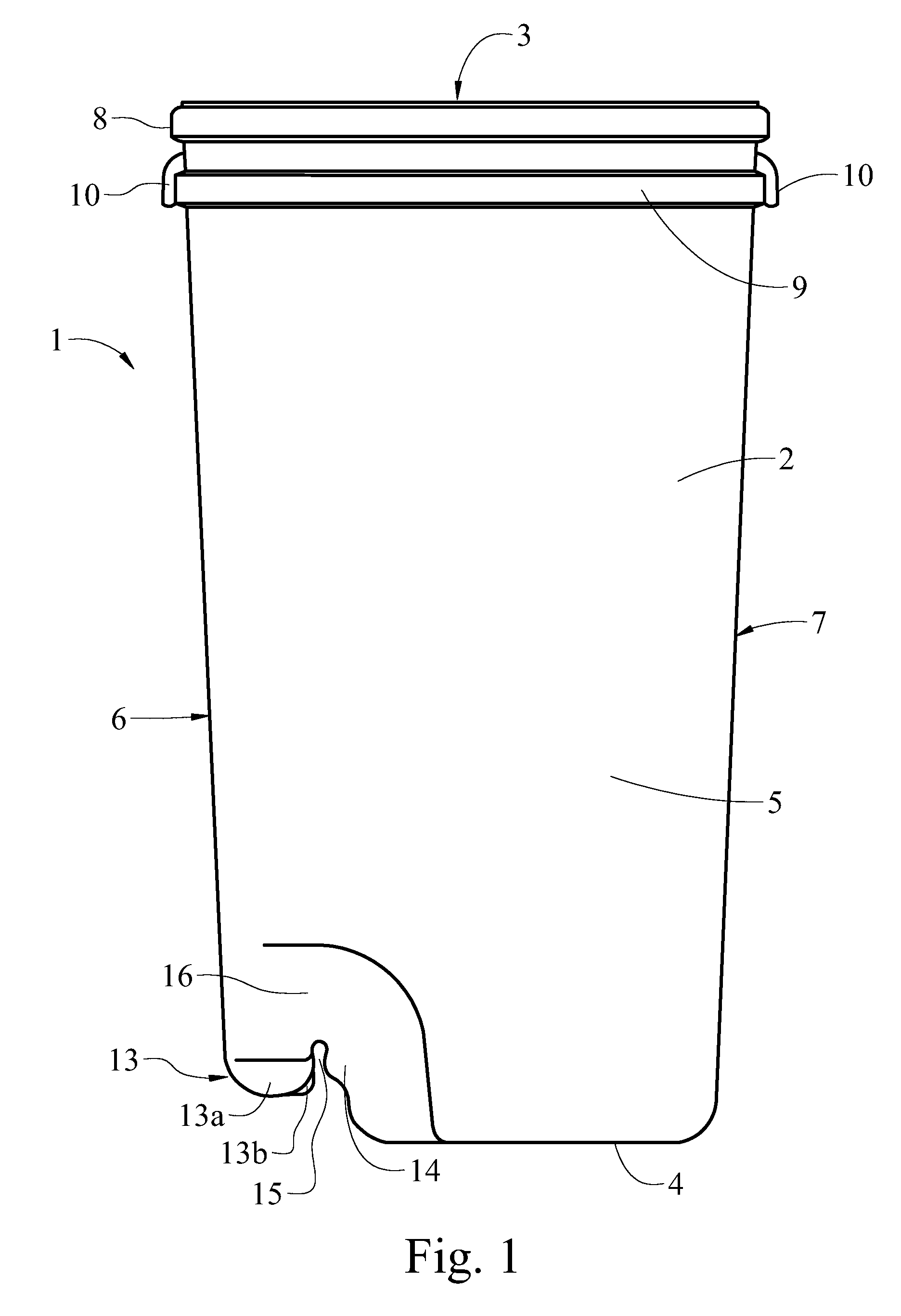
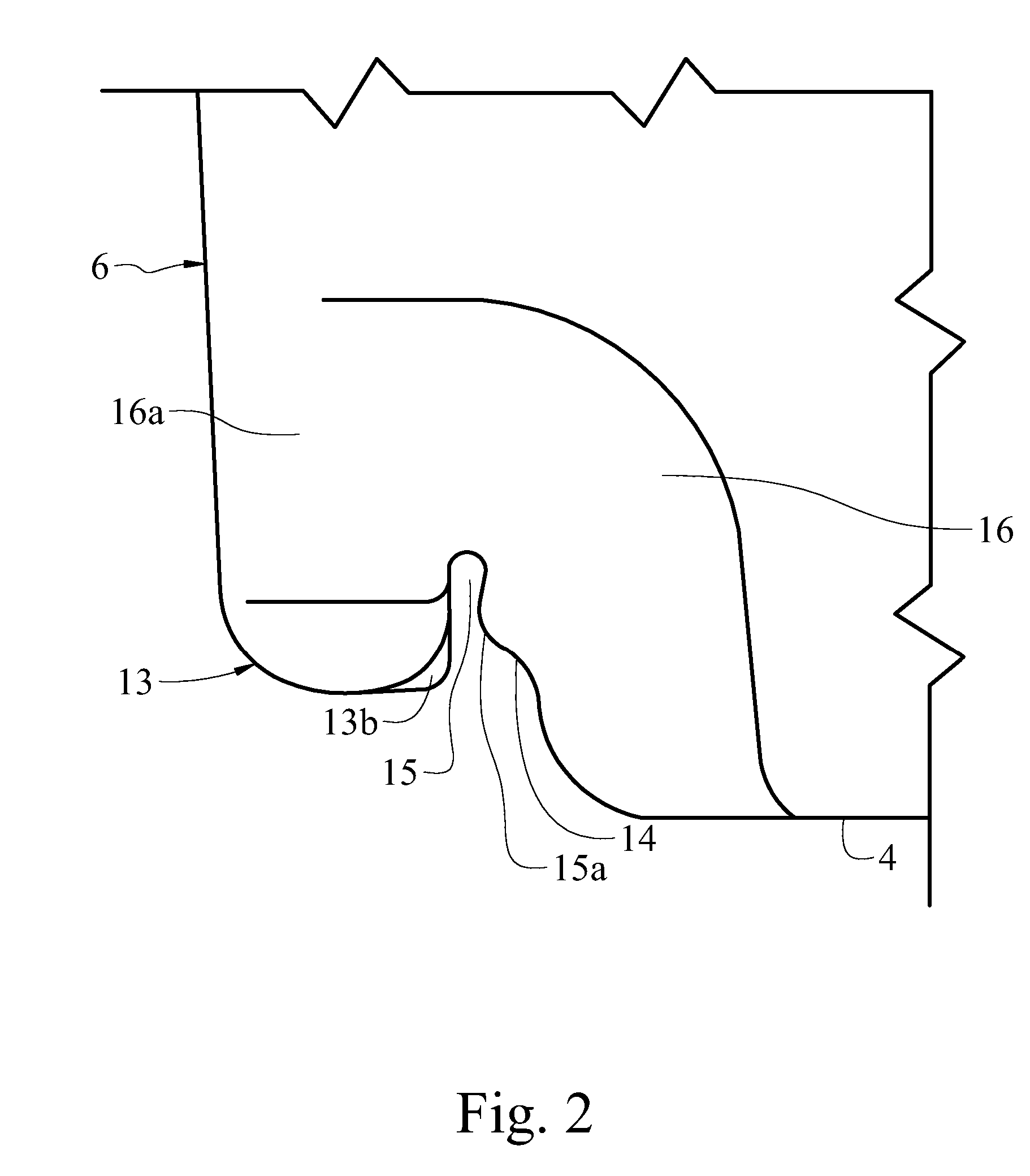
[0032] The present art overcomes the prior art limitations by having two ribs at the opening and positioning the axle closer to the center of the bottom of the can. In FIG. 1, the wheeled can 1 begins with a container 2 having an open top 3 and an opposite closed bottom 4 joined by four walls, the front 6 and opposite back 7, and two sidewalls 5. The top has a width and a depth to fit within the gap at the end of a bar. Generally the top is approximately 11 inches wide and 19 inches deep. The bottom is narrower in width and depth than the top. The width and depth of the container taper between the top and the bottom. Proximate to the top, the container has a first rib 8 on the exterior that occupies the perimeter of the container. In the preferred embodiment, the first rib 8 is approximately ¾ inch in height. Mutually parallel and spaced below the first rib 8, a second rib 9 occupies the perimeter. Where the second rib occupies the front 6 and the back 7, the second rib 9 has a hand...


PUM


Abstract

A wheeled can fits within the width and depth at the end of a bar. The can has a generally hollow container with an open top and a closed bottom. The top has a width and a depth to fit within a narrow and limited opening at the end of a bar. The can has two reinforcing ribs and at least one handle. The can tapers downwards for its length on both the width and the depth of the container. The bottom is generally narrower than the top. Near the bottom, two corners are recessed and curved to accept a wheel and include a slot for an axle. In use, the wheels fit within the width and depth established by the top and within the front and the back at the bottom. The wheels allow staff to remove the wheeled can from a confined space readily.

Description

CROSS-REFERENCE TO RELATED APPLICATION [0001] This is a non-provisional application claiming priority to the provisional application with a serial No. of 60 / 710,978 which was filed on Aug. 24, 2005 and is commonly owned by the same inventor.BACKGROUND OF THE INVENTION [0002] The wheeled can relates generally to a refuse container, and more specifically, one that fits within the confined space of a bar or other establishment. The wheeled can may be blow molded, or injection molded, from a polymer. A unique aspect of the present invention is wheels upon an axle that fit within the footprint of the top of the wheeled can. The wheeled can has attributes that allow for its swift assembly, from a minimum of parts, but yet have substantial reinforcement that lengthens the useful life in a demanding environment. [0003] As a day draws to a close, people emerge from workplaces and homes across the land for in search of refreshment. The search often takes people to a restaurant, bar, or other ...

Claims


Application Information

Patent Timeline
Patent Type & Authority Applications(United States)
IPC IPC(8): B62B1/00
CPCB65F1/02B65F2220/12B65F1/1468B65F1/1473
Inventor YOUNG, ROGER L.
Owner YOUNG ROGER L
Why Eureka
Try Eureka