Techniques for folded tag antennas

a technology of antennas and tags, applied in the field of folded antennas of radio frequency identification devices, can solve the problems of high density webs directly at odds with tag performance, difficult trade-offs, and low cost of end product, so as to improve multi-axis performance, improve multi-axis performance, and reduce web material

Active Publication Date: 2007-03-01
RUIZHANG TECH LTD CO
View PDF12 Cites 48 Cited by
  • Summary
  • Abstract
  • Description
  • Claims
  • Application Information

AI Technical Summary

Benefits of technology

[0007] Techniques for an RFID device with improved multi-axis performance are provided. The device, in one embodiment, includes a flexible substrate with an antenna pattern thereon. The antenna pattern can be elongated with a major axis of the pattern being significantly longer than a minor axis. A fold in the flexible substrate orients a port

Problems solved by technology

Densely packed webs reduce the quantity of web material consumed, and thus the cost of the end product.
In some instances, high density webs are directly at odds with tag performance.
Thi

Method used


Image

  • Techniques for folded tag antennas
  • Techniques for folded tag antennas
  • Techniques for folded tag antennas

Examples


Embodiment Construction

[0026] The following description and drawings are illustrative of the invention and are not to be construed as limiting the invention. Numerous specific details are described to provide a thorough understanding of the present invention. However, in certain instances, well known or conventional details are not described in order to avoid obscuring the description of the present invention. References to one or an embodiment in the present disclosure are not necessarily references to the same embodiment; and, such references mean at least one.

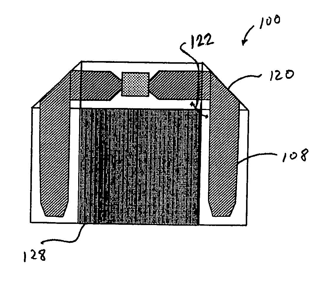
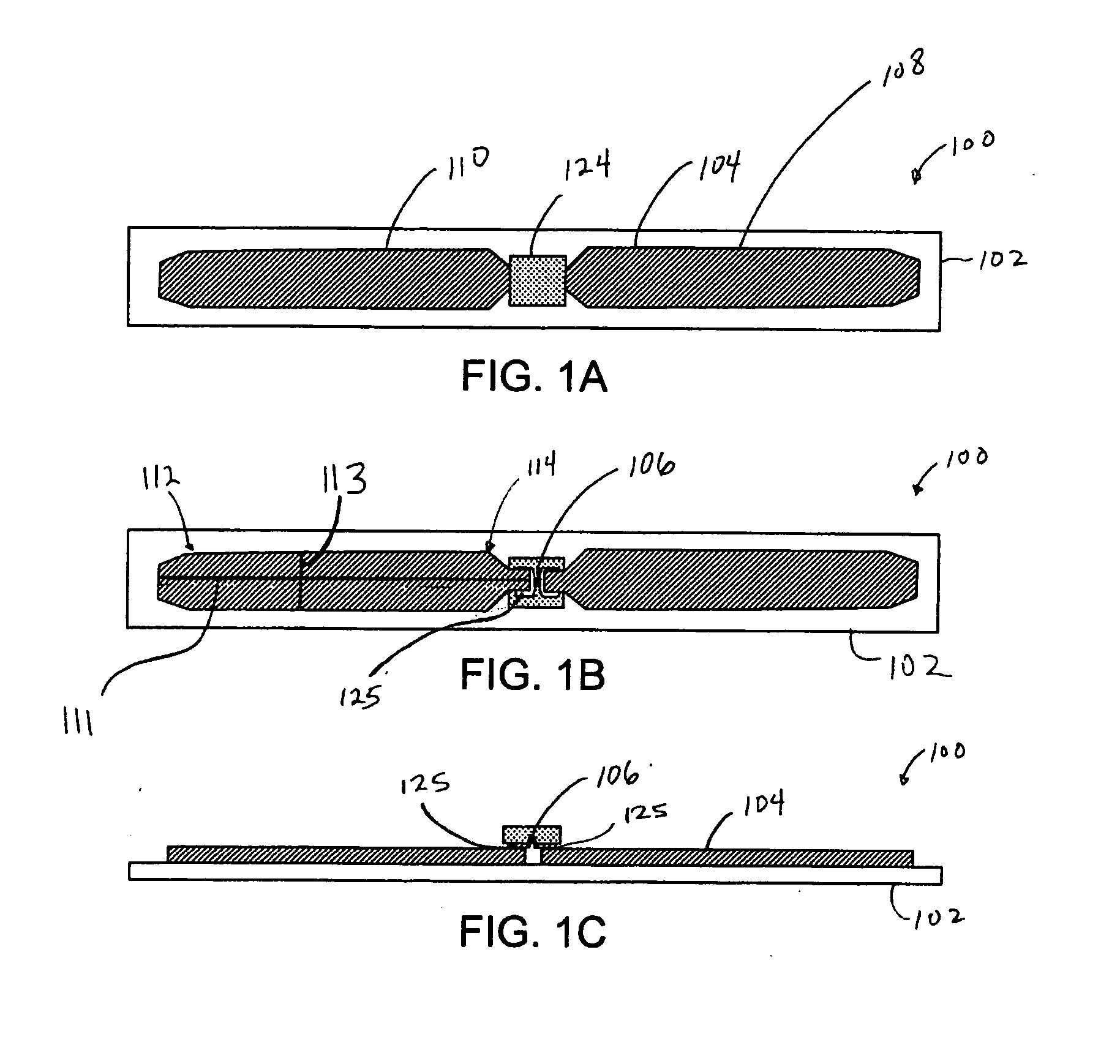
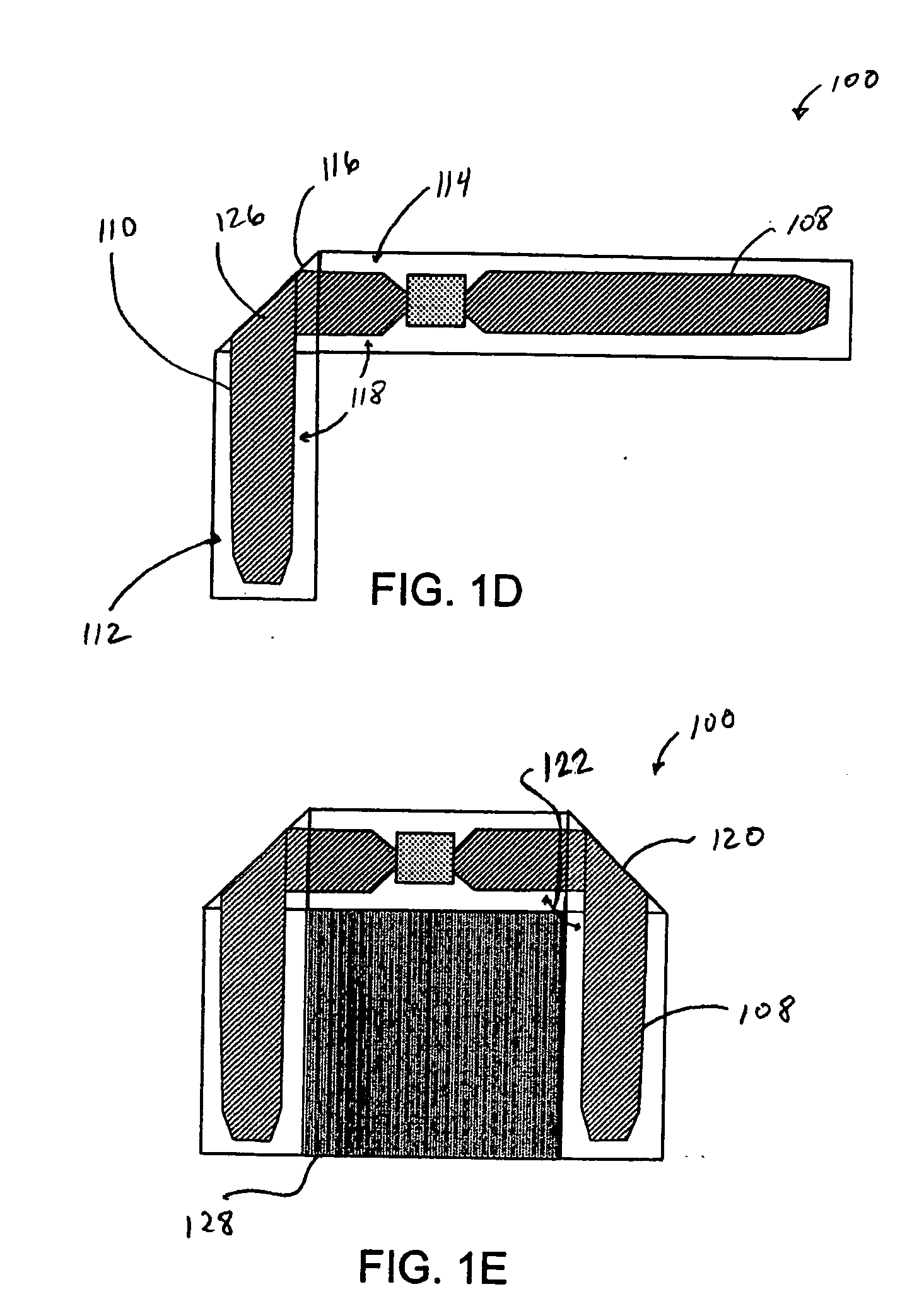
[0027] Inlays, also referred to as inlets, include at least an integrated circuit (IC) and antenna on a substrate. Inlays can be made into tags (inlays with a protective over laminate) or converted into finished smart (RFID) labels. FIGS. 1A-1E illustrate an RFID inlay 100 according to an embodiment of the present invention. Top, bottom, and cross-sectional views of inlay 100 are respectively shown in FIGS. 1A-1C. Inlay 100 includes a substrate 1...


PUM


Abstract

Techniques for an RFID device with improved multi-axis performance are provided. The device includes a flexible substrate with an antenna pattern formed thereon. A fold in the flexible substrate results in the antenna pattern crossing over itself and disposes a distal region of the antenna pattern away from a proximal region at about a predetermined angle. An integrated circuit is electrically coupled to the antenna pattern. In a specific embodiment, the antenna pattern is slit along a major axis to allow folding a segment of an antenna pattern.

Description

FIELD OF THE TECHNOLOGY [0001] This application claims the benefit of prior U.S. provisional patent application No. 60 / 713,898, filed Sep. 1, 2005. The present invention generally relates to the field of radio frequency identification (RFID) devices, and particularly to RFID devices having folded antennas and methods for making same.BACKGROUND [0002] Goods and other items may be tracked and identified using an RFID system. An RFID system includes a tag and a reader. The tag is a small transponder typically placed on an item to be tracked. The reader, sometimes referred to as an interrogator, includes a transceiver and an antenna. The antenna emits electromagnetic (EM) waves generated by the transceiver, which, when received by tag, activates the tag. Once the tag activates, it communicates using radio waves back to reader, thereby identifying the item to which it is attached. [0003] There are three basic types of RFID tags. A beam-powered tag is a passive device which receives energ...

Claims


Application Information

Patent Timeline
IPC IPC(8): G08B13/14
CPCG08B13/24H01Q1/20H01Q1/2225G06K19/0779H01Q9/26H01Q9/285H01Q9/24
Inventor CARRENDER, CURTIS
Owner RUIZHANG TECH LTD CO
Why Eureka
Try Eureka