EL display apparatus and drive method of EL display apparatus

a technology of display apparatus and drive method, which is applied in static indicating devices, instruments, cathode ray tubes/electron beam tubes, etc., can solve problems such as display irregularities, display irregularities, display irregularities, etc., and achieve the effect of avoiding insufficient writing and avoiding insufficient writing

Active Publication Date: 2007-03-01
JAPAN DISPLAY CENT INC
View PDF5 Cites 50 Cited by
  • Summary
  • Abstract
  • Description
  • Claims
  • Application Information

AI Technical Summary

Benefits of technology

[0030] A target tone voltage is determined using the measured voltage as a variable value for a function which determines tone for the video signal. By applying the determined tone voltage to the source signal line 18, the driving transistors in the selected pixel row is programmed so that a target current will flow through the EL element 15. Thus, the signal corresponding to the video signal applied to the pixel 16 is a voltage sign...

Problems solved by technology

However, an organic EL display panel uses transistor arrays made of low-temperature or high-temperature polysilicon, and variations in the characteristics of the transistors in the polysilicon transistor arrays of organic E...

Method used


Image

  • EL display apparatus and drive method of EL display apparatus
  • EL display apparatus and drive method of EL display apparatus
  • EL display apparatus and drive method of EL display apparatus

Examples


Embodiment Construction

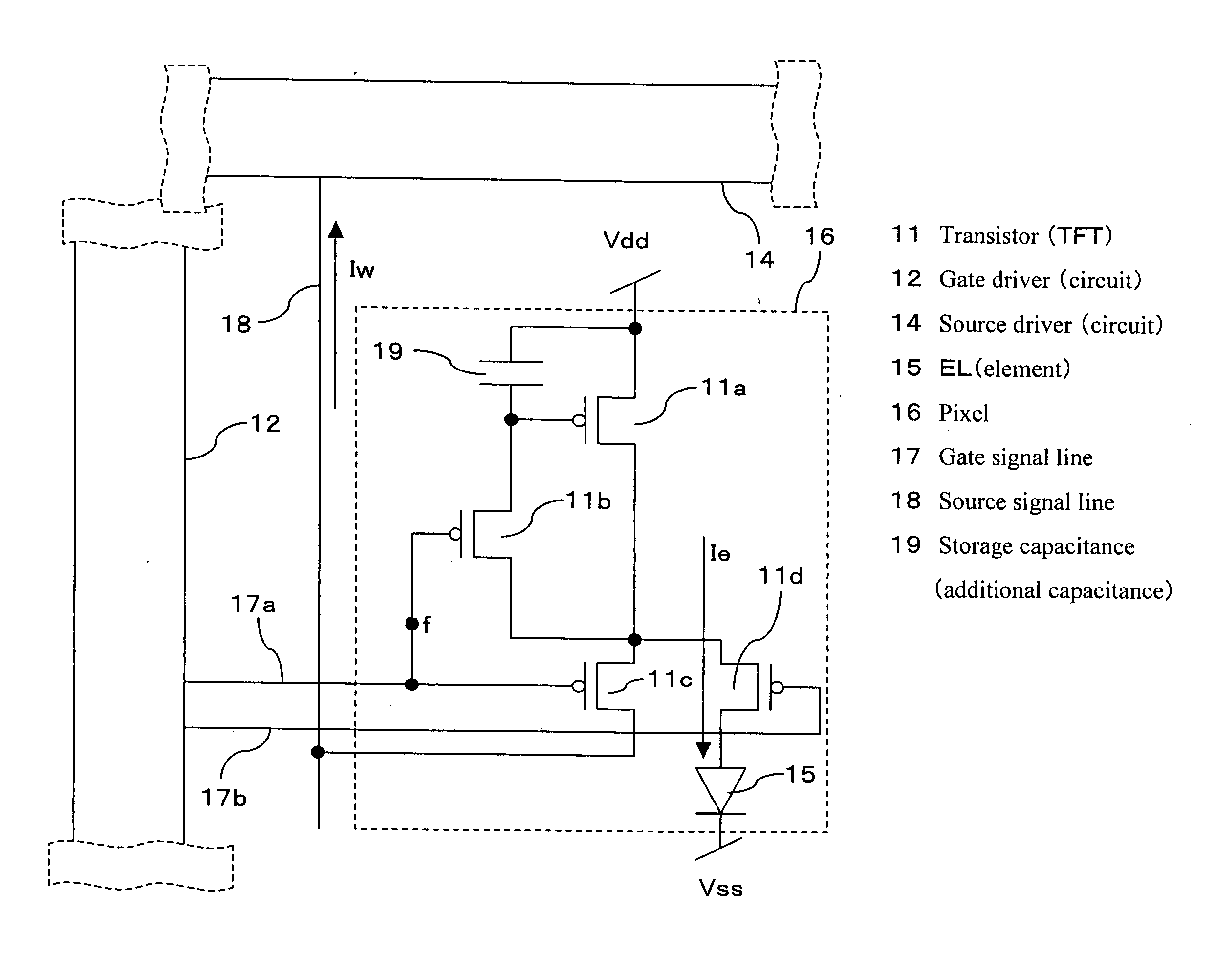
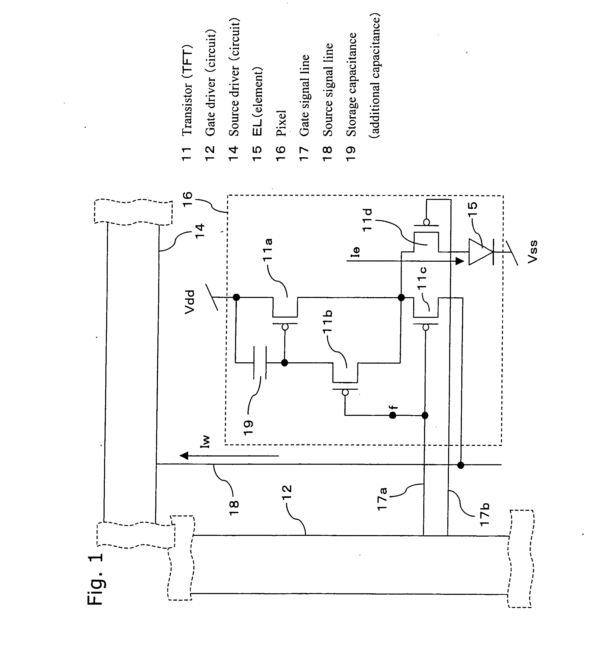
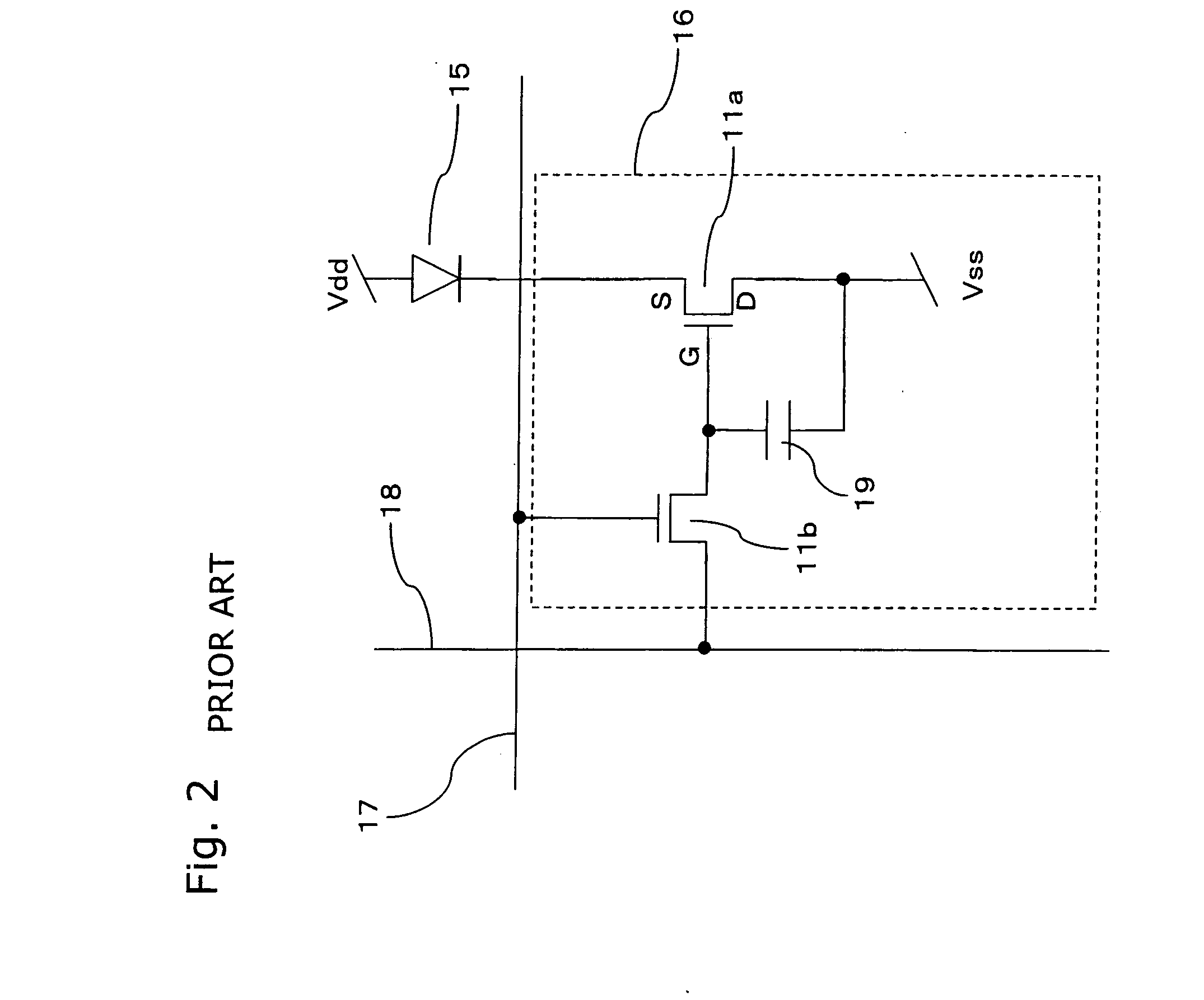
[0276] Some parts of drawings herein are omitted and enlarged and / or reduced herein for ease of understanding and illustration. Besides, the same or similar forms, materials, functions, or operations are denoted by the same reference numbers or characters.

[0277] Thin-film transistors are cited herein as driver transistors 11a and switching transistors 11b, and the like, this is not restrictive. Thin-film diodes (TFDs) or ring diodes may be used instead. Also, the present invention is not limited to thin-film elements, and transistors formed on silicon wafers may also be used. Needless to say, transistors may also be FETs, MOS-FETs, MOS transistors, or bipolar transistors. It goes without saying that the present invention may also use diodes, varistors, thyristors, ring diodes, photodiodes, phototransistors, or PLZT elements.

[0278] A source driver circuit (IC) 14 is not only a mere driver but may incorporate a power circuit (charge pump circuit, DCDC converter circuit), buffer circ...


PUM


Abstract

A precharge voltage Vp is applied in period A. The precharge voltage Vp is generated by applying a constant current Iw to a pixel driving transistor of a display panel and using gate terminal voltage of the driving transistor which passes the constant current Iw. The gate terminal potential is held in memory. When displaying images on a display panel, the gate terminal potential is read out of memory, and used as the precharge voltage Vp after arithmetic processing. By the application of the precharge voltage Vp, a source signal line is charged and discharged quickly so that an almost target tone current will flow through the driving transistor. Furthermore, a more accurate program current is written into the pixel during period B.

Description

BACKGROUND OF THE INVENTION [0001] 1. Field of the Invention [0002] The present invention relates to EL display apparatus and drive method of EL display apparatus which employs a self-luminous display panel (display apparatus) such as an EL display panel (display apparatus) using organic or inorganic electroluminescent (EL) elements, or the like. [0003] 2. Related Art of the Invention [0004] With active-matrix image display apparatus which employ an organic electroluminescent (EL) material or an inorganic EL material as an electrochemical substance, emission brightness changes according to current written into pixels. An EL display panel is of a self-luminous type in which each pixel has a light-emitting element. EL display panels have the advantages of being more viewable than liquid crystal display panels, having high light emission efficiency, requiring no backlighting, having high response speed, etc. [0005] Such an organic EL display panel of an active-matrix type is disclosed ...

Claims


Application Information

Patent Timeline
IPC IPC(8): G09G3/30
CPCG09G3/2081G09G2320/0261G09G3/3241G09G3/325G09G3/3283G09G3/3291G09G2300/0842G09G2300/0852G09G2300/0861G09G2310/0221G09G2310/0235G09G2310/0248G09G2310/0251G09G2310/0297G09G2320/0233G09G3/3233E03F5/0407E03F2005/0417
Inventor TAKAHARA, HIROSHI
Owner JAPAN DISPLAY CENT INC
Why Eureka
Try Eureka