Direct type backlight device for liquid crystal module

a backlight device and liquid crystal panel technology, applied in the direction of point-like light sources, lighting and heating apparatuses, instruments, etc., to achieve the effect of suppressing brightness unevenness, good balance, and increasing brightness

Inactive Publication Date: 2007-03-01
FUNAI ELECTRIC CO LTD
View PDF10 Cites 35 Cited by
  • Summary
  • Abstract
  • Description
  • Claims
  • Application Information

AI Technical Summary

Benefits of technology

[0014] With the present invention, it is preferable if the crosspiece has a peaked cross sectional shape with a peak, and a surface of the peak of the crosspiece is the light reflecting surface. The light from the linear light sources that hits the crosspiece is reflected toward both the light diffuser plate and the spaces between adjacent linear light sources. As a result, a good balance is maintained between the amount of light incident on the light diffuser plate and the increase in brightness between the linear light sources. Accordingly, brightness unevenness on the display screen of the liquid crystal panel is even more dramatically suppressed.
[0015] With the present invention, it is preferable if the frame is rectangular, and the linear light sources and the crosspiece extend in a longitudinal direction of the rectangular frame. The result of this is that the role of the crosspiece as a structural member dramatically improves the warping resistance of an oblong frame of a direct type backlight device corresponding to the oblong screens that are found on many television receivers that make use of a liquid crystal module.
[0016] With the present invention, it is preferable if a plurality of protrusions that protrude toward the light diffuser plate are spaced apart in a row along the crosspiece, and a top of each of the protrusions is proximal to and across from the light diffuser plate. Even though the height of the crosspiece is reduced and its shadow can therefore be prevented from falling on the light diffuser plate, when the light diffuser plate is bent so as to bulge toward the inside of the frame, the bending deflection amount is restricted to a microscopic extent by the tops of the protrusions. Therefore, it is possible to suppress the decrease in image quality that would otherwise be caused by the bending deflection of the light diffuser plate.
[0017] With the present invention, it is preferable if, when the light diffuser plate is bent from its original position so as to bulge toward the inside of the frame, the tops of the protrusions hit a bulging region of the light diffuser plate so that a bending deflection amount of the light diffuser plate is restricted. There is n

Problems solved by technology

With this configuration, even if the resin molding frame is made larger and there is a problem where the frame might not h

Method used


Image

  • Direct type backlight device for liquid crystal module
  • Direct type backlight device for liquid crystal module
  • Direct type backlight device for liquid crystal module

Examples


Embodiment Construction

[0028] A preferred embodiment of the present invention will now be explained with reference to the drawings. It will be apparent to those skilled in the art from this disclosure that the following description of the preferred embodiment of the present invention is provided for illustration only and not for the purpose of limiting the invention as defined by the appended claims and their equivalents.

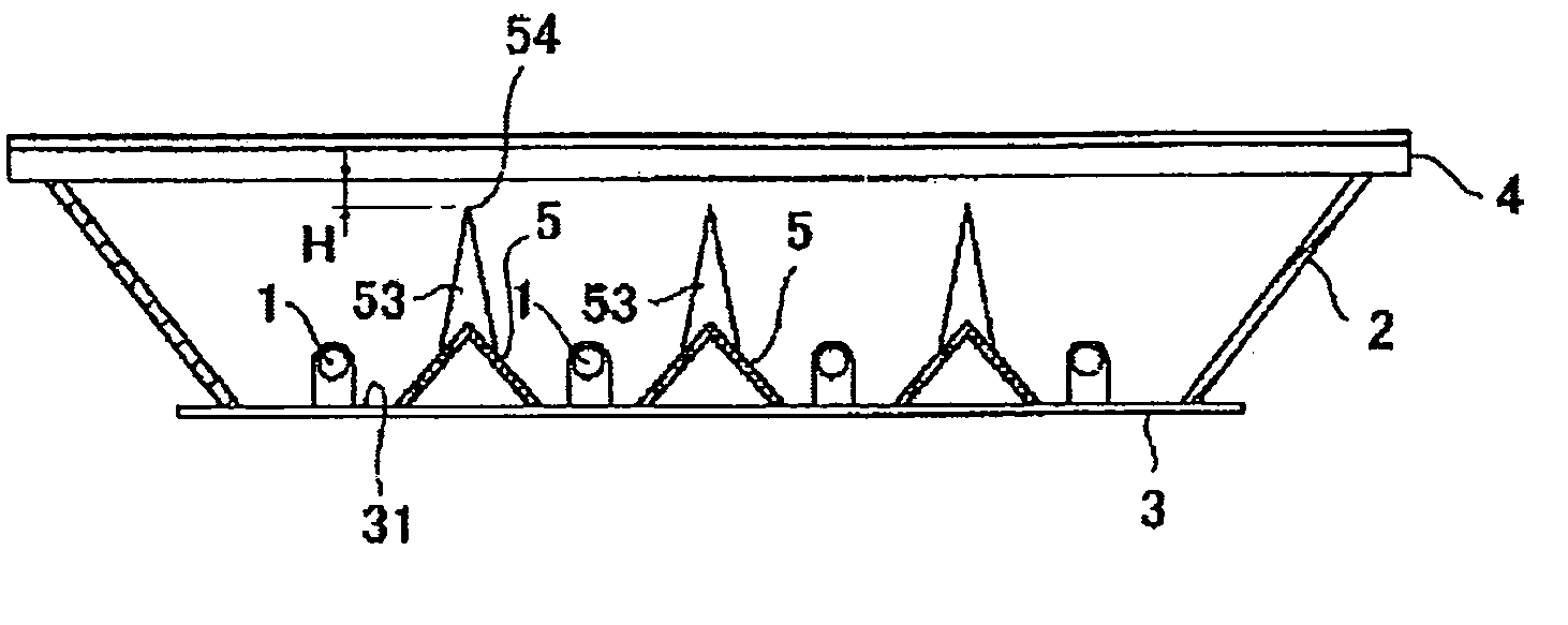
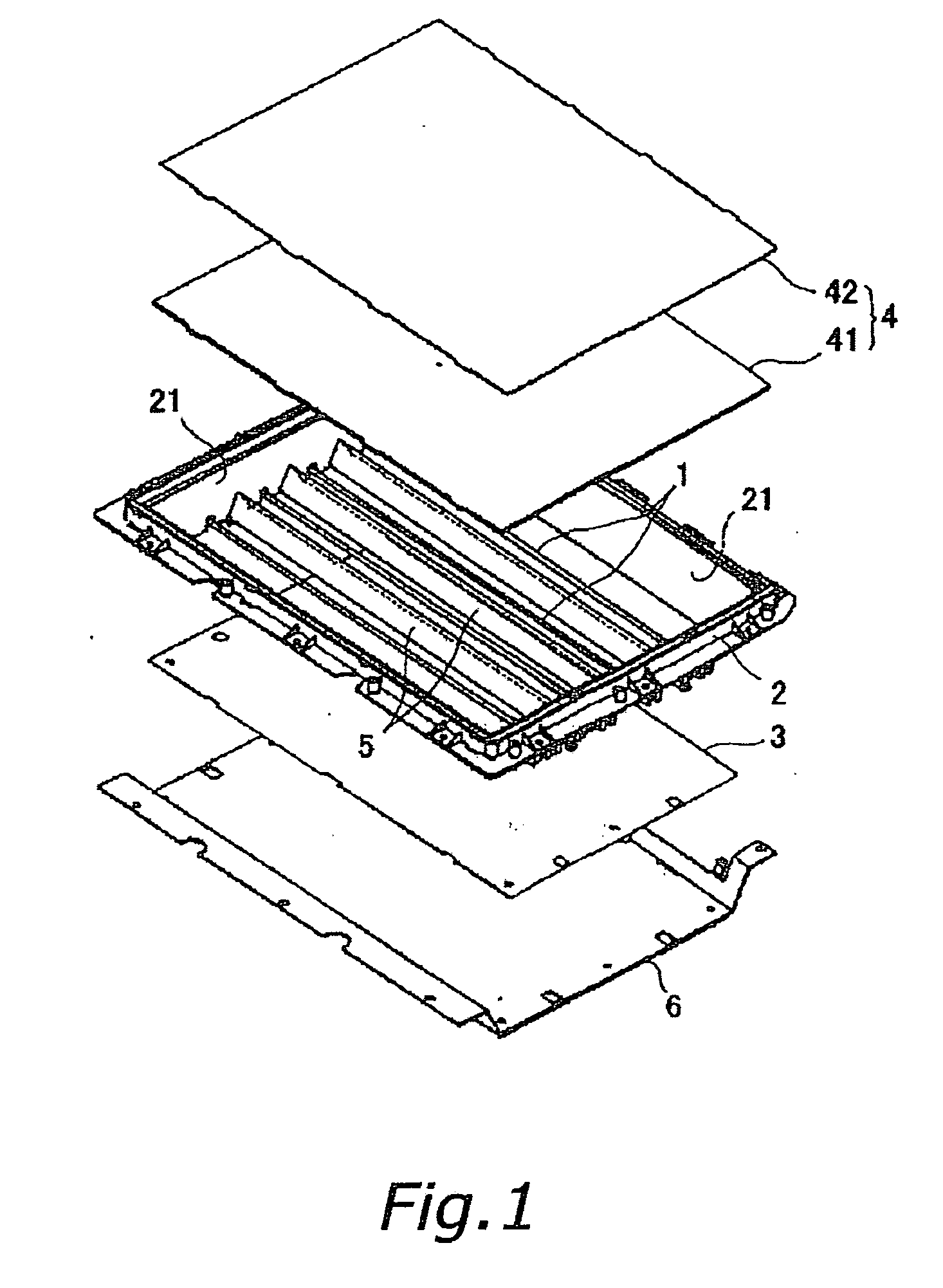
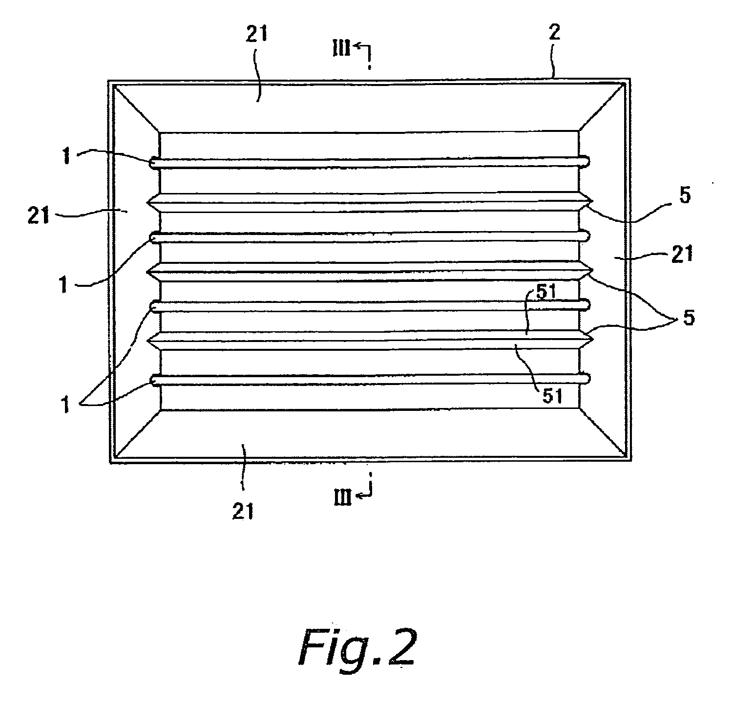
[0029] As shown in FIG. 1, a direct type backlight device includes linear light sources 1, a rectangular frame 2 to which the linear light sources 1 are attached, a reflective sheet 3, a light diffuser plate 4 and a back plate 6 made of sheet metal. The reflective sheet 3 and the diffuser plate 4 are provided on opposite sides of the frame 2. The light diffuser plate 4 is constituted by a main plate 41 of high rigidity and a sheet 42. The main plate 41 and the sheet 42 are superposed one over the other.

[0030] With this direct type backlight device, the linear light sources 1 are formed ...


PUM


Abstract

A direct type backlight device for a liquid crystal module having a liquid crystal panel includes a resin molded frame, a reflective sheet, a light diffuser plate and at least one crosspiece. The resin molded frame attaches linear light sources in parallel at a plurality of sites spaced apart. The reflective sheet is disposed on one side of the frame. The light diffuser plate is disposed on another side of the frame. The crosspiece is fixed to the frame between adjacent linear light sources and has a light reflecting surface. Light transmitted through the light diffuser plate illuminates the liquid crystal panel.

Description

CROSS-REFERENCE TO RELATED APPLICATIONS [0001] This application claims priority to Japanese Patent Application No. 2005-248889. The entire disclosure of Japanese Patent Application No. 2005-248889 is hereby incorporated herein by reference. BACKGROUND OF THE INVENTION [0002] 1. Field of the Invention [0003] The present invention generally relates to a direct type backlight device for a liquid crystal module. More specifically, the present invention relates to a direct type backlight device for a liquid crystal module having a liquid crystal panel. [0004] 2. Background Information [0005] A liquid crystal module has a reflective sheet, a light diffuser plate and a frame (a resin molding). The reflective sheet and the light diffuser plate sandwich the frame. A plurality of linear light sources (fluorescent tubes) are attached to the frame. The light emitted from the linear light sources is reflected by the reflective sheet. The light is also diffused by the light diffuser plate so that...

Claims


Application Information

Patent Timeline
IPC IPC(8): F21V7/00
CPCG02F1/133604G02F1/133608G02F1/133605
Inventor SUDO, TATSUJI
Owner FUNAI ELECTRIC CO LTD
Why Eureka
Try Eureka