Input/output router for storage networks

Active Publication Date: 2007-03-01
AVAGO TECH INT SALES PTE LTD
View PDF23 Cites 89 Cited by
  • Summary
  • Abstract
  • Description
  • Claims
  • Application Information

AI Technical Summary

Benefits of technology

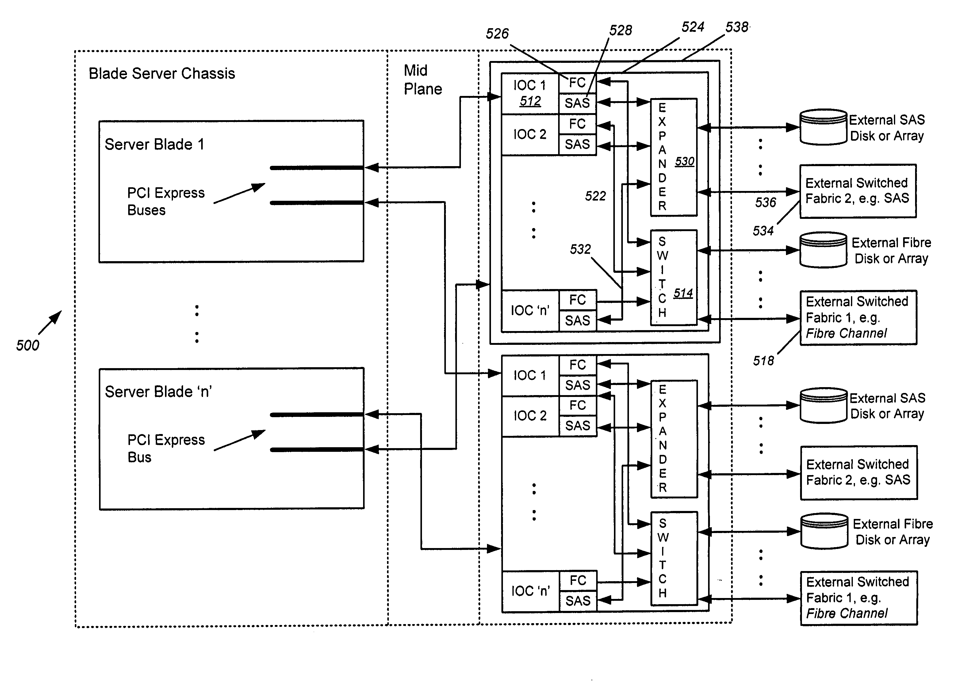
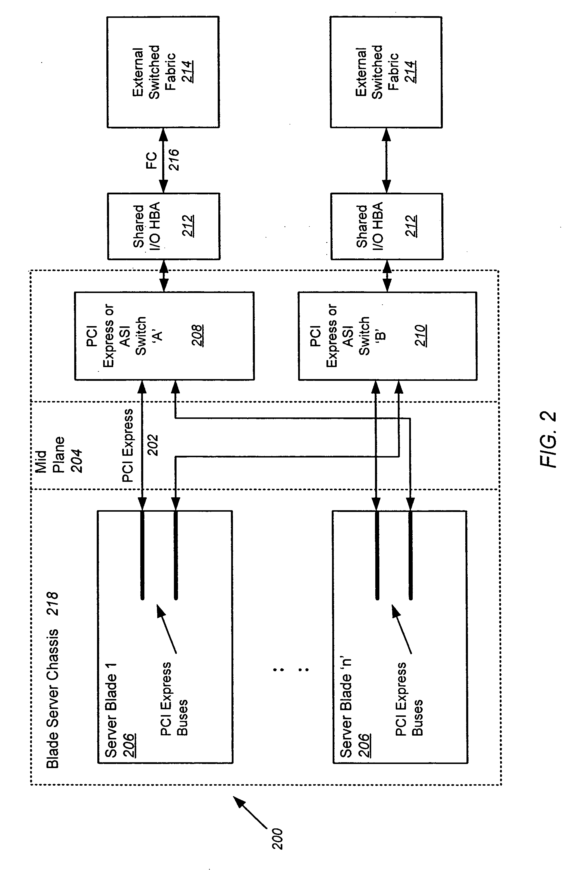
[0015] Embodiments of the present invention are directed to a blade server comprised of multiple server blades that plug into a midplane from the front of the blade server chassis, and an I / O router including multiple IOCs (one for each server blade) and an embedded switch that plugs into the midplane from the back of the blade server chassis. The midplane carries PCI Express lanes for connecting the server blades to the I / O router. Each of the IOCs is physically couplable to a server blade over a separate PCI Express connection in the midplane. Each IOC is also coupled to the embedded switch via an internal FC link within the I / O router. Each embedded switch contains one or more ports, some of which connect to each of the IOCs over the internal FC links, and some of which provide external FC links that may connect to an external switched fabric or directly to a network attached device.

Problems solved by technology

Because a full fabric switch with an E_PORT is counted as a hop, this configuration does not address three hop limitation concerns.

Method used


Image

  • Input/output router for storage networks
  • Input/output router for storage networks
  • Input/output router for storage networks

Examples


Embodiment Construction

[0027] In the following description of preferred embodiments, reference is made to the accompanying drawings which form a part hereof, and in which it is shown by way of illustration specific embodiments in which the invention may be practiced. It is to be understood that other embodiments may be utilized and structural changes may be made without departing from the scope of the preferred embodiments of the present invention.

[0028] Although embodiments of the present invention are described herein in terms of FC signaling, it should be understood that the present invention is not limited to FC, but includes InfiniBand, Ethernet, Serial Attached Small Computer System Interconnect (SAS) signaling and the like. Implementation of these protocols requires that the midplane support the protocols.

[0029]FIG. 3 illustrates an exemplary blade server 300 according to embodiments of the present invention. The blade server chassis 302 includes multiple (e.g. 8-14) server blades 304 that plug i...


PUM


Abstract

A blade server is disclosed, comprised of multiple server blades that plug into a midplane from the front, and an I/O router including multiple IOCs (one for each server blade) and an embedded switch that plugs into the midplane from the back. The midplane carries PCI Express lanes for connecting the server blades to the I/O router. Each of the IOCs is physically couplable to a server blade over a separate PCI Express connection in the midplane, preserving existing driver compatibility, and is coupled to the embedded switch via an internal FC link within the I/O router. Each embedded switch may contain full fabric services ports. Alternatively, the full fabric services may be left out, and N_PORT virtualization or FC_AL stealth mode may be employed to allow the embedded switch to interoperate transparently with the external fabric switch and eliminate the third hop in the blade server chassis.

Description

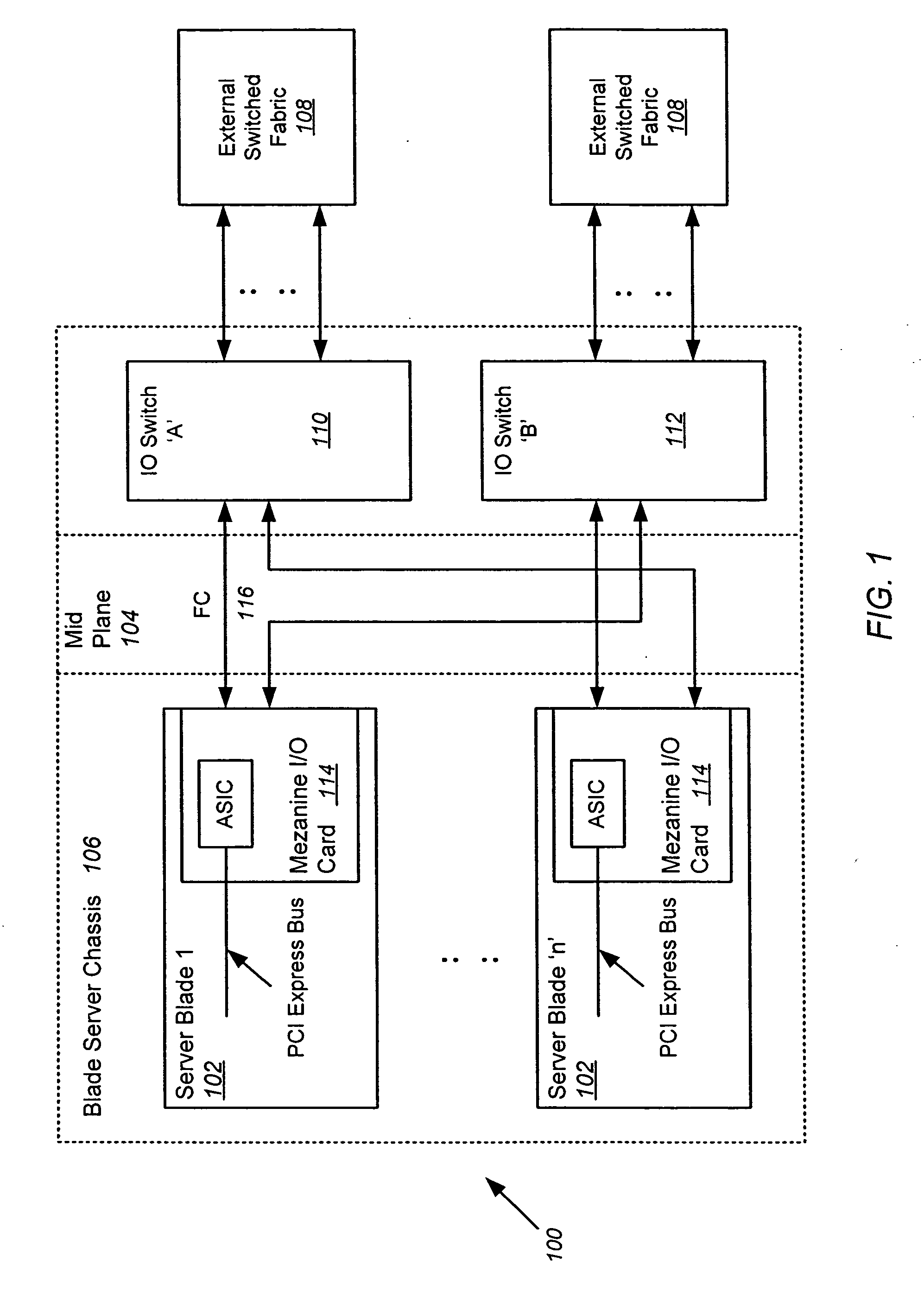
FIELD OF THE INVENTION [0001] This invention relates to blade servers coupled to an external switched fabric or network device, and more particularly, to an Input / Output (I / O) router for enabling communications between server blades in the blade server and devices connected to the external switched fabric or network device. BACKGROUND OF THE INVENTION [0002] Conventional blade servers. FIG. 1 is an exemplary illustration of a conventional blade server 100 connected to an external switched fabric. Blade servers overcome some of the inefficiencies of individual standalone or rack-mounted one unit (1U) high servers, each of which is self-contained and includes separate power supplies, fans, and the like. Individual servers are therefore inefficient in terms of space, power, cooling, and other characteristics. Blade servers 100 utilize a modular, plug-in approach wherein the housing for each server is eliminated along with self-contained components such as power supplies and fans. Each ...

Claims


Application Information

Patent Timeline
Patent Type & Authority Applications(United States)
IPC IPC(8): H04L12/50
CPCH04L49/357H04L49/358H04L49/602H04L49/552H04L49/40
Inventor SCHERER, GREGORY JOHNMULVANY, KAREN
Owner AVAGO TECH INT SALES PTE LTD
Why Eureka
Try Eureka