Face mask and goggle system

a technology of goggles and masks, applied in the field of protective gear, can solve the problems of difficult to easily and efficiently replace and/or clean the lenses when necessary, and the known face mask and goggle systems suffer from various inadequacies, and achieve the effect of new and effective arrangemen

Active Publication Date: 2007-03-08
KORE OUTDOOR US INC
View PDF62 Cites 34 Cited by
  • Summary
  • Abstract
  • Description
  • Claims
  • Application Information

AI Technical Summary

Benefits of technology

[0055] It is preferable that the width of the central receiving slot 46 is sized (in its non-flexed or non-deformed state) to be about the thickness of the lens 48. When the mask body 12 is flexed such as by moving the opposing sides 14, 16 closer to each other, and the central portion 44 and area adjacent the grooves 38a, 38b is flexed or deformed. With the nose portion 66 of the lens 48 in the receiving slot 46, the flanges 64a, 64b can pass by the surface of the area adjacent the grooves 38a, 38b, such as channel walls 40a and 40b, into the receiving grooves 38a, 38b. Once the flanges 64a, 64b snap into place in the grooves 38a, 38b, the nose portion 22 and nose extensions 68a, 68b can drop further into and be seated in the central receiving slot 46. The nose extensions 68a, 68b are supported at or adjacent to the bottom of the slot 46, as shown in FIG. 10. This provides a firm locking or snapping engagement of the nose portion 22 and flanges 64a, 64b into the mask body 12. Releasing the mask body 12 and allowing it to return to its non-deformed, non-flexed, normal state provides an even tighter engagement of the full length of the flanges 64a, 64b with the receiving grooves 38a, 38b. It is preferred that a user would not be able to remove the lens 48 from its engagement with the mask body without flexing or otherwise deforming the mask body 12.
[0056] This engagement further assists in fixing the lens 48 in place when in use. It is appreciated that, due to the design of the present invention, this arrangement will firmly hold the lens 48 in place on the mask body 12. The face mask system 10 of the present invention comprises even further means for maintaining the lens in place attached to the mask body, as discussed below.
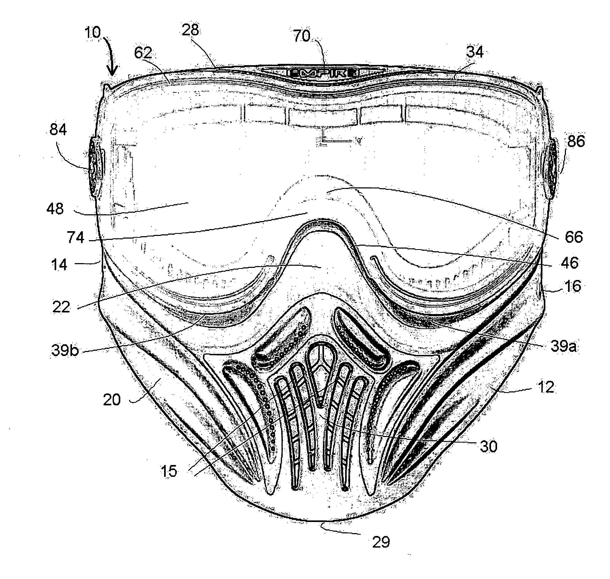
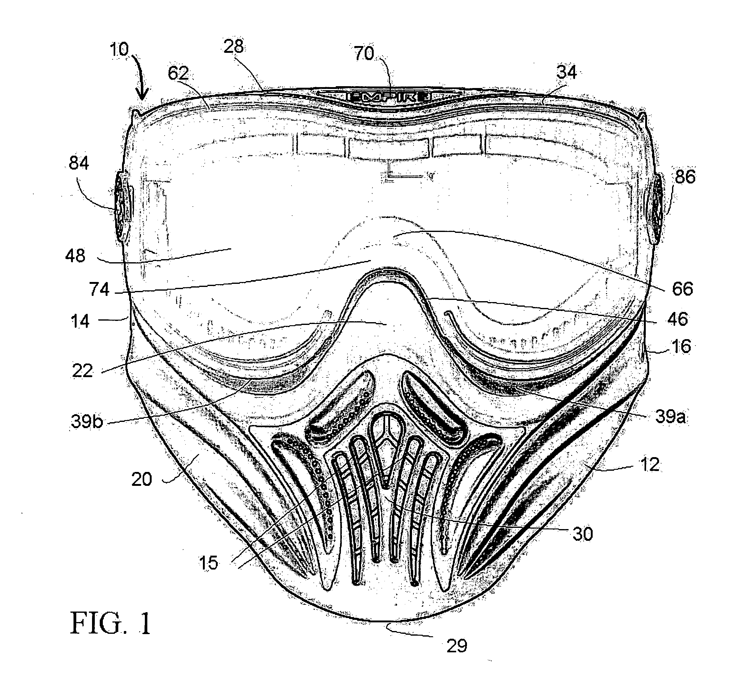
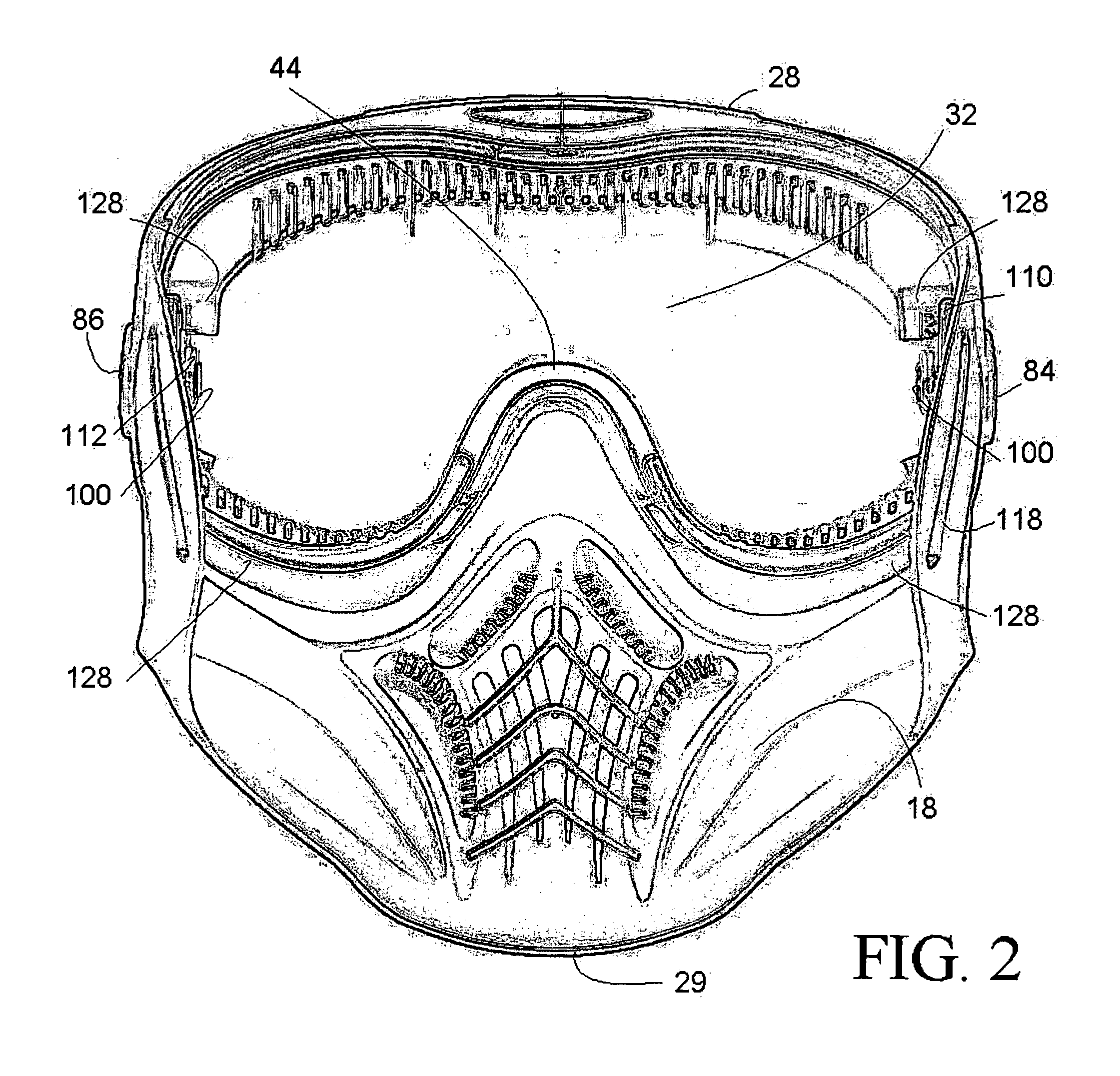
[0057] As shown in FIGS. 1-4, a central portion 70 of the upper portion 28 may extend or otherwise slope downward, and engage a receiving portion 72 in the middle of the upper portion 50 of the lens 48. The upper flange 62 of the lens 48 is received within the upper receiving groove 36. Because the mask body 12 is formed from a flexible material, the upper flange 62 of the lens 48 can additionally snap into the upper receiving groove 36. This provides an additional alignment means for maintaining the lens 48 in the correct position on the mask body 12.
[0058] According to a further feature of the present invention, the central portion 44 of the lens supporting portion 34 is formed so that, in its normal orientation, the central portion 44 is higher than (raised or above) the nose portion 22, as shown in FIGS. 4 and 20. The central portion 44 may be formed having a central support wall 74, which is a generally flat, U-shaped surface against which the nose portion 66 of the lens 48 can rest and / or be supported by from the rear. Thus, the lens 48 is supported from behind by the central portion 44 and central support wall 74 when the lens 48 is attached to the mask body 12, such as when the nose extensions 68a and 68b are engaged with the central receiving slot 46. This provides a novel and effective arrangement that prevents the lens 48 from displacing in relation to the mask body 12 if impacted by a projectile. If, for example, a projectile (such as a paintball) were to impact the lens 48 adjacent the nose portion 22 of the mask body 12 or the nose portion 66 of the lens 48, the mask body 12 and lens 48 will not separate. The lens 48 will be supported from behind by the central support wall 74, and the mask body 12 will not be moved away from the lens 48 or otherwise create a penetrable space or opening. The lens 48 is also supported within the slot 46 at its front by the nose portion 22. The arrangement of the present invention prevents the lens 48 from moving or otherwise being dislodged along its edges, as the nose extensions 68a and 68b are held within the central receiving slot 46, and the upper flange 62 and the lower flanges 64a, 64b engage the respective receiving grooves 36 and 38a, 38b.

Problems solved by technology

Known face mask and goggle systems suffer from various inadequacies.
Current face masks and goggles have complicated arrangements for attaching lenses to the body of the face mask or goggle.
These known face masks and goggles make it is difficult to easily and efficiently replace and / or clean the lenses when necessary.
Furthermore, current face mask and goggle systems do not have an acceptable arrangement for aligning the lenses on the bodies or frames of the face mask and goggle systems.

Method used


Image

  • Face mask and goggle system
  • Face mask and goggle system
  • Face mask and goggle system

Examples


Embodiment Construction

[0042] The present invention is directed to a novel face mask and lens arrangement, that provides increased protection to a user, and can be easily assembled or disassembled. In another embodiment, the present invention is directed to a goggle and lens system. The protective face mask 10 is described herein with the right side 14 and left side 16 from the perspective of a user wearing the face mask 10, with each side 14, 16 being essentially a mirror image of the opposite side. The inner side (or inner surface) 18 is that side facing a user wearing the face mask 10, and the outer side 20 is that side facing away from the user.

[0043] As shown in FIGS. 1-4 and 20, a face mask 10 according to the present invention includes a mask body 12, having a nose portion 22, opposite temple portions 24 (left side), temple portions 26 (right side), an upper portion 28, and a mouth portion 30. The mask body 12 is formed from a semi-rigid or flexible material, such as a rubber or plastic, or other ...


PUM


Abstract

A protective face mask system according to the present invention comprises a flexible mask body including an opening for receiving a lens, nose portion, a central portion positioned to the rear of and extending at least partially above the nose portion, a central receiving slot located between the nose portion and the central portion, right and left temple portions, each temple portion having a shaped receiving opening therethrough, left and right cheek portions, and at least one groove located adjacent one of the left and right cheek portions. A lens is provided sized to be received upon and cover the lens opening. The lens includes right and left temple portions including openings therein positioned to correspond to and align with the openings of the mask body when the lens is positioned for attachment to the mask body. The lens including at least a portion that snappingly engages the groove when a portion of the lens is inserted into the slot.

Description

CROSS REFERENCE TO RELATED APPLICATION [0001] This application claims priority from U.S. Provisional Patent Application No. 60 / 682,566, the entire contents of which is incorporated by reference as if fully set forth herein.FIELD OF INVENTION [0002] The present invention generally relates to the field of protective gear, and more specifically, to the field of protective face mask and goggle systems for sports. BACKGROUND [0003] Paintball is a popular sporting game. It is played on a field including obstacles. Generally, teams of players each have a flag located at the team's home base. The object of the game is to “capture” the opposing team's flag before they capture yours. Each player is armed with a paintball marker for firing projectiles. Most paintball markers are compressed gas guns that shoot projectiles, otherwise known as paintballs. Paintballs are generally spherical gelatin capsules filled with paint, normally a non-toxic marking dye. If a player is hit with and marked by ...

Claims


Application Information

Patent Timeline
Patent Type & Authority Applications(United States)
IPC IPC(8): A61F9/02
CPCA42B3/20A61F9/029A61F9/028
Inventor STEVENS, SIMON BENJAMIN
Owner KORE OUTDOOR US INC
Why Eureka
Try Eureka