
Trigger mechanism for firearms with self-loading actions

a trigger mechanism and firearm technology, applied in the field of trigger mechanisms, can solve the problems of rifles firing without the intent of the operator, noise and motion is considered undesirable, and the occurrence of “cook-off” under extended heavy fire rate, etc., and achieve the effect of no undesirable noise or motion

Inactive Publication Date: 2007-03-08
COLT CANADA IP HLDG PARTNERSHIP
View PDF11 Cites 105 Cited by
  • Summary
  • Abstract
  • Description
  • Claims
  • Application Information

AI Technical Summary

Benefits of technology

[0008] One aspect of the invention is that it allows the firearm to operate in a closed-bolt mode during semi-automatic fire (when accuracy is desirable) and operate in an open-bolt mode (when high heat conditions exist) to avoid possible cook-offs. The mode change occurs when the first round is discharged after the selector has been moved instead of when the selector switch is moved, and thus there is no undesirable noise or motion as in the prior art.

Problems solved by technology

The drawback of a closed-bolt rifle is the occurrence of “cook-off” under extended heavy rates of fire.
This is a dangerous condition where the rifle may fire without the intent of the operator.
However, while switching from open-bolt mode (automatic) to closed-bolt mode, there is a loud mechanical motion of the carrier to the closed-bolt position.
This noise and motion is considered undesirable from the operator's standpoint in terms of sound signature while trying to maintain stealth, and potential surprise / confusion over the motion of the carrier.

Method used


Image

  • Trigger mechanism for firearms with self-loading actions
  • Trigger mechanism for firearms with self-loading actions
  • Trigger mechanism for firearms with self-loading actions

Examples


Embodiment Construction

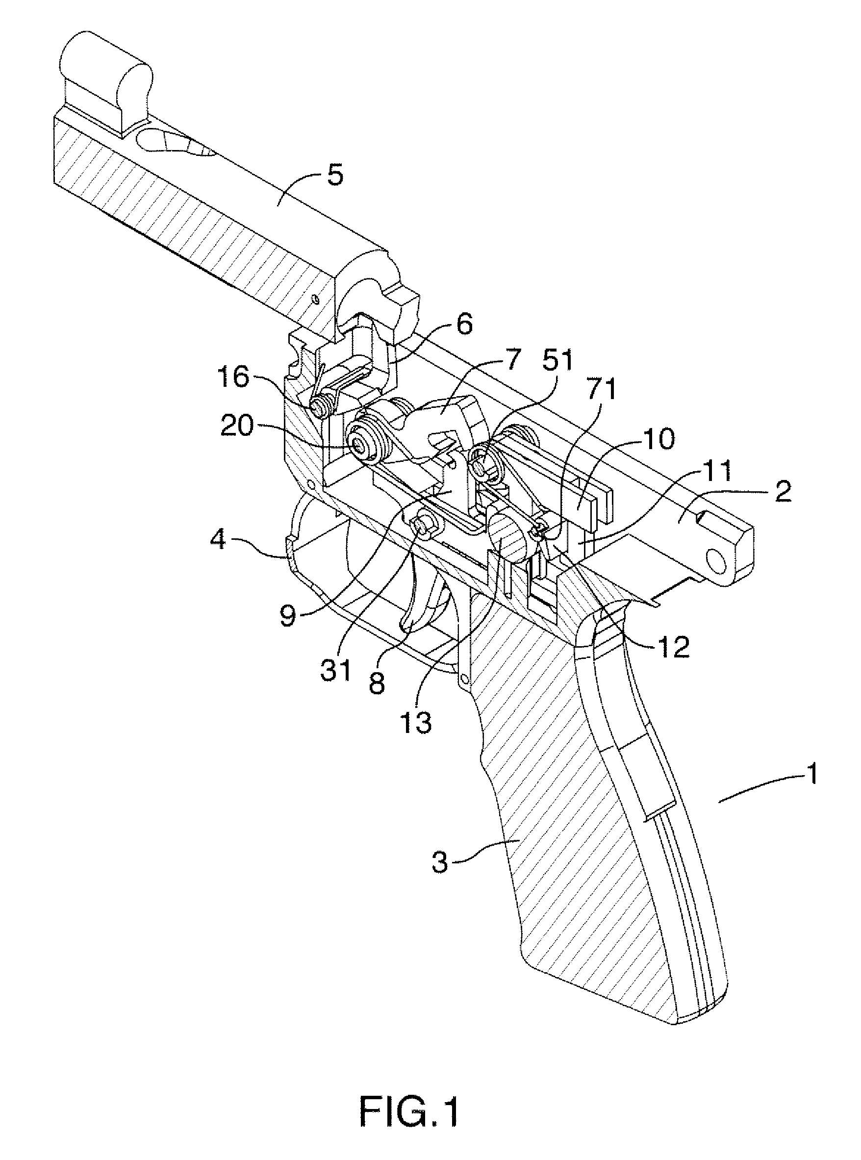
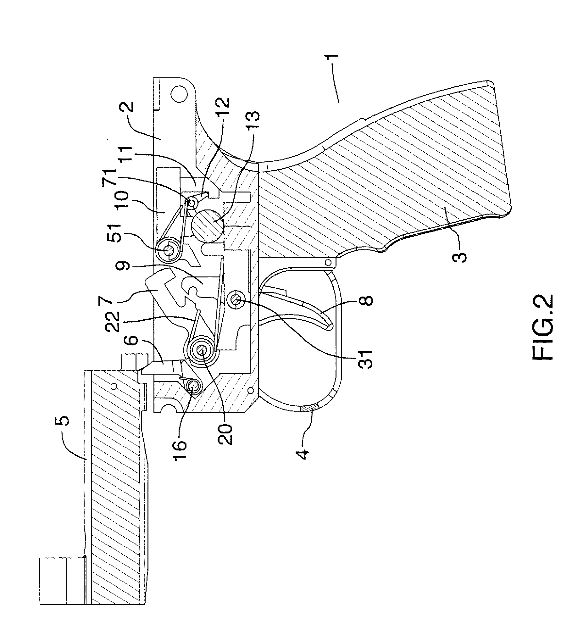
[0039] Referring now to the accompanying drawings, the preferred embodiment will be described in detail. It should be understood that this is an example of the invention only, and that other embodiments and variations are possible within the scope of the invention.

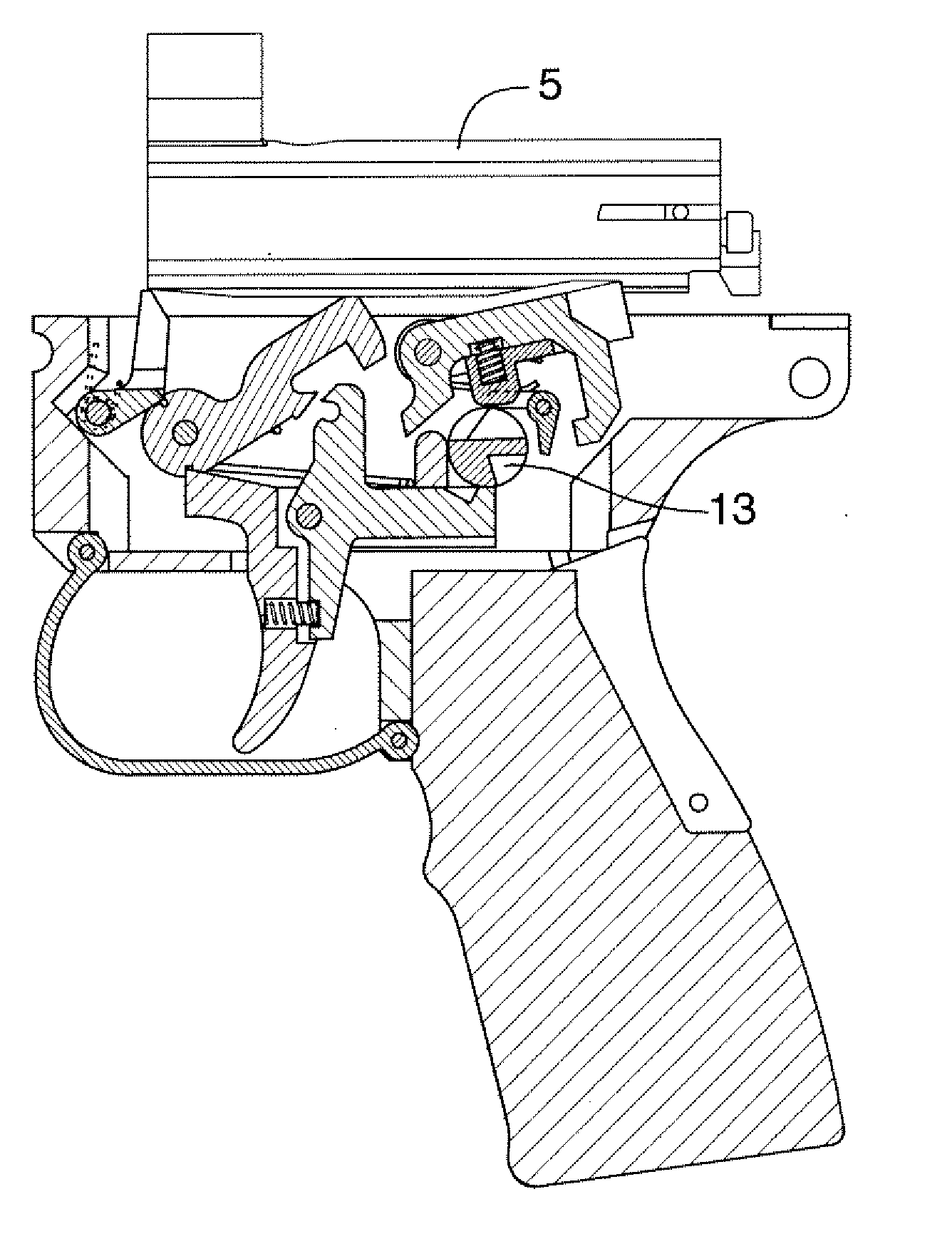
[0040]FIGS. 1-3 show the primary components of the trigger mechanism, embodied in a rifle 1. For simplicity, many conventional elements of the rifle are not illustrated, other than the receiver 2, grip 3, trigger guard 4, and carrier 5. The main components for operation of the invention are the auto-sear 6, the hammer 7, the trigger 8, the disconnect 9, the carrier sear 10, the safety sear 11, the auto-disconnect 12, and the selector 13.

[0041] The preceding main components of the preferred embodiment will be described first, followed by a description of closed-bolt operation, then open-bolt operation, then the mechanism which integrates the two modes of operation and permits switching between them.

Components of the Pref...


PUM


Abstract

The trigger mechanism allows the firearm to operate in a closed-bolt mode during semi-automatic fire and in an open-bolt mode during automatic fire. The mode change occurs only after the first round is discharged after the selector has been moved instead of when the selector switch is moved, thus avoiding undesirable mechanism noise or motion at the time of selecting the firing mode.

Description

REFERENCE TO RELATED APPLICATION [0001] This is a formal application based on and claiming the benefit of United States provisional patent application no. 60 / 713,722, filed Sep. 6, 2005.BACKGROUND OF THE INVENTION [0002] This invention relates to firearms and weapons in general and in particular to a trigger mechanism particularly intended for firearms with self-loading actions. [0003] Self-loading actions are those where the next round loads after a round has been discharged, whether semi-automatic or automatic. Once the firearm is cocked, the operator must only pull the trigger to fire a round and load the next available round from a magazine, belt or other storage device. As long as there is ammunition available the firearm will be ready to fire the next time the operator pulls the trigger. [0004] Self-loading firearms operate either in open-bolt or closed-bolt fashion. This refers to the position of the bolt and carrier. The bolt houses the firing pin and locks together with the...

Claims


Application Information

Patent Timeline
Patent Type & Authority Applications(United States)
IPC IPC(8): F41C7/00
CPCF41A19/46F41A17/16
Inventor GROVES, G.FRANKLIN, E.
Owner COLT CANADA IP HLDG PARTNERSHIP
Learn More