Manufacturing Method For Friction Material Products
a friction material and manufacturing method technology, applied in the field of friction material products, can solve the problems of large volume of gas, back effect, cracks, etc., and achieve the effect of maintaining the quality of friction material and reducing the molding step
Inactive Publication Date: 2007-03-08
NISSHINBO IND INC
View PDF8 Cites 9 Cited by
- Summary
- Abstract
- Description
- Claims
- Application Information
AI Technical Summary
Benefits of technology
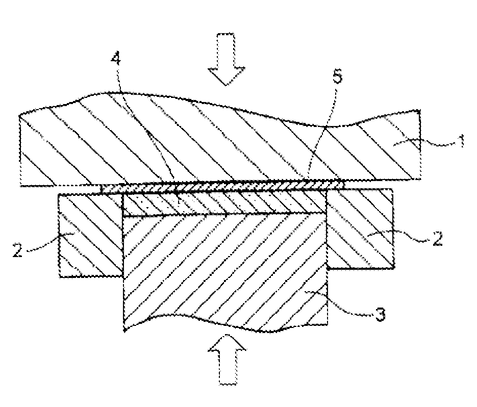
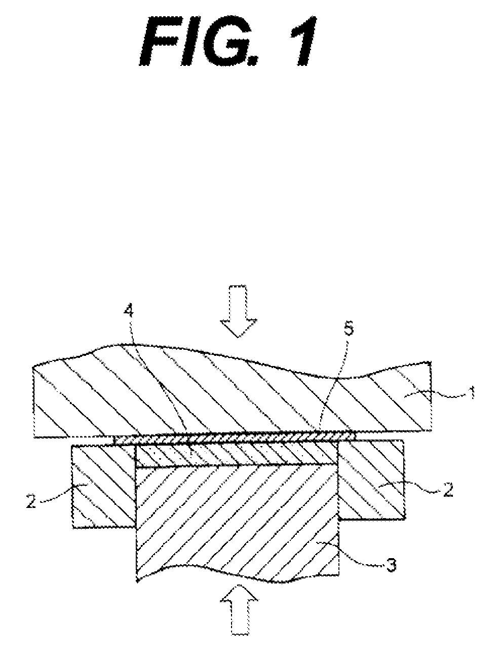
[0006] In order to attain the above-object, inventors of this invention initially focused on the die temperature and tried to increase the die temperature of the current molding die so as to shorten the reaction time of the thermosetting resin. However, a simple step of increasing the die temperature did not allow the resin to reach to the entire fricton material, which left some portions with small binding force among the raw friction materials, or rapidly generated a large volume of gas within the friction material, where depressurizing as outgassing releases the raw friction material in a direction of its thickness, thereby causing the spring back effect. Accordingly, it was found that cracks have been generated in a worst scenario. Therefore, in addition to the increase of the die temperature, a molding pressure was increased to a great extent comparing to the conventional step. Then, it was found that no spring back effect occurred even if the molding time was greatly shortened from the conventional molding time of 5 minutes-15 minutes to 2 minutes or less when the die temperature was set to be 190° C. or higher and the molding pressure was set to be 100 MPa or higher. This phenomenon is considered do to a resin flow within the raw friction material. That is, in comparison to the resin flow under the conventional combination of the die temperature and pressure, the resin flow under the condition of the greatly increased die temperature and the molding pressure becomes much larger (faster). In the case that the resin flow is large (fast), it is estimated that the resin tends to smoothly reach though gaps among the raw friction materials (such as fiber base material and filler), which eliminates the portion with small binding force among the raw friction materials in the short period of time, and that the resin reaches to the entire friction material as pushing the gas outside the friction material, which eliminates a possibility of leaving the gas within the friction material.
[0013] The manufacturing method of the present invention provides the manufacturing method for the friction material products which does not require the special molding die and realizes a significant reduction of molding step while maintaining the quality of the friction material.
Problems solved by technology
However, a simple step of increasing the die temperature did not allow the resin to reach to the entire fricton material, which left some portions with small binding force among the raw friction materials, or rapidly generated a large volume of gas within the friction material, where depressurizing as outgassing releases the raw friction material in a direction of its thickness, thereby causing the spring back effect.
Accordingly, it was found that cracks have been generated in a worst scenario.
Method used
View moreImage
Smart ImageViewing Examples
Examples
embodiments
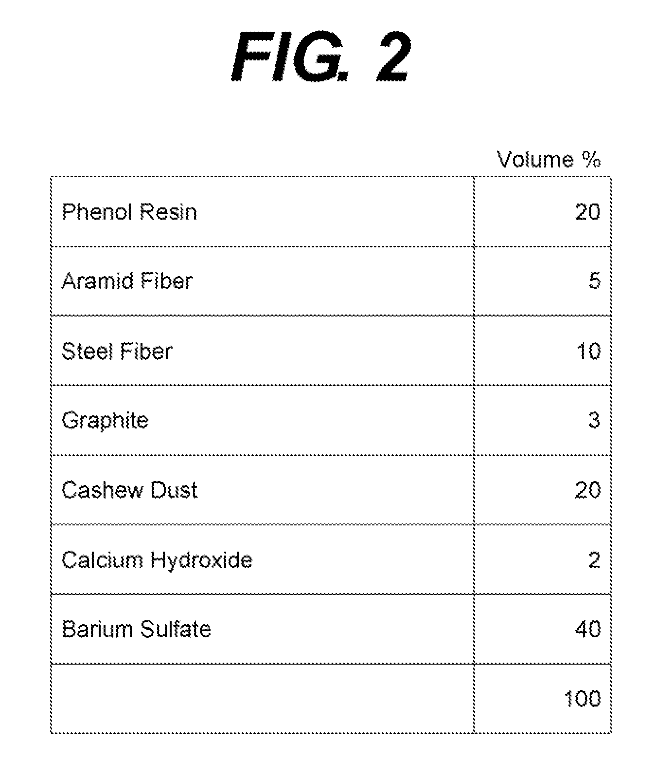
[0027] Embodiments and comparative examples will be shown below for more concrete explanation of the present invention; however, the present invention is not limited to the embodiments described below.
Login to View More PUM
| Property | Measurement | Unit |
|---|---|---|
| Temperature | aaaaa | aaaaa |
| Pressure | aaaaa | aaaaa |
| Friction | aaaaa | aaaaa |
Abstract
To provide the manufacturing method for the friction material products which does not require the special molding die and realizes the significant simplification of the molding step while maintaining the quality of the friction material. The manufacturing method for the friction material products comprising the molding step of pressurizing and heating to mold the molding material made of the raw friction material within the molding die, wherein the molding temperature in the molding step is 190° C.-230° C. and the pressure thereof is 100 MPa-200 MPa.
Description
FIELD OF THE INVENTION [0001] This invention relates to friction material products preferably used for such as a disc pad and a brake lining for such as an automobile and a heavy duty truck. BACKGROUND OF THE INVENTION [0002] Among various friction material products, there are products such as the disc pad comprised of the friction material fixed on a back plate and the brake lining which is the friction material as itself. Generally, the friction material products are produced through a “mixing step” where the raw friction material made of such as a fiber base material, filler, and resin (binder) are evenly mixed with a mixer such as Redige mixer and Eirich mixer, a “preliminarily forming step” where a preliminarily formed product is made as filling the respective mixed materials of fixed quantity in a metal die and is pressurized by a pressing device, a “molding step” where the preliminarily formed product is pressurized and heated by another pressing device, (wherein for the disc...
Claims
Login to View More Application Information
Patent Timeline
 IPC IPC(8): B27N3/00
CPCB29C43/003B29C43/18B29K2303/04B29L2031/7482B29K2503/06B29K2705/00B29L2031/16B29K2503/04B29C43/56B29C43/02
Inventor CHIBA, MASANORIISHII, YASUJI
Owner NISSHINBO IND INC
Features
- R&D
- Intellectual Property
- Life Sciences
- Materials
- Tech Scout
- Unparalleled Data Quality
- Higher Quality Content
- 60% Fewer Hallucinations
Learn More Browse by: Latest US Patents, China's latest patents, Technical Efficacy Thesaurus, Application Domain, Technology Topic, Popular Technical Reports.
© 2025 PatSnap. All rights reserved.Legal|Privacy policy|Modern Slavery Act Transparency Statement|Sitemap|About US| Contact US: help@patsnap.com


