Liquid crystal display and method for manufacturing the same

Inactive Publication Date: 2007-03-08
SAMSUNG ELECTRONICS CO LTD
View PDF12 Cites 1 Cited by
  • Summary
  • Abstract
  • Description
  • Claims
  • Application Information

AI Technical Summary

Benefits of technology

[0019] A height of the rising may b

Problems solved by technology

The liquid crystal may flow to the edges of the two panels, for example, along a perimeter of the panels, resulting in a non-uniform distribution of the liquid crystal such that the cell gap may be non-uniform.
The liquid crystal may be contaminated by directly contacting an unhardened sealant in an assembly process for combining the two panels.
The liquid crystal may be damaged by ultraviolet rays when the sealant is hardened by the ultraviolet rays.

Method used


Image

  • Liquid crystal display and method for manufacturing the same
  • Liquid crystal display and method for manufacturing the same
  • Liquid crystal display and method for manufacturing the same

Examples


Embodiment Construction

[0040] Exemplary embodiments of the present invention will be described in more detail with reference to the accompanying drawings. The present invention may, however, be embodied in many different forms and should not be construed as limited to the embodiments set forth herein.

[0041] A liquid crystal display according to an embodiment of the present invention is described with reference to FIGS. 1 to 3.

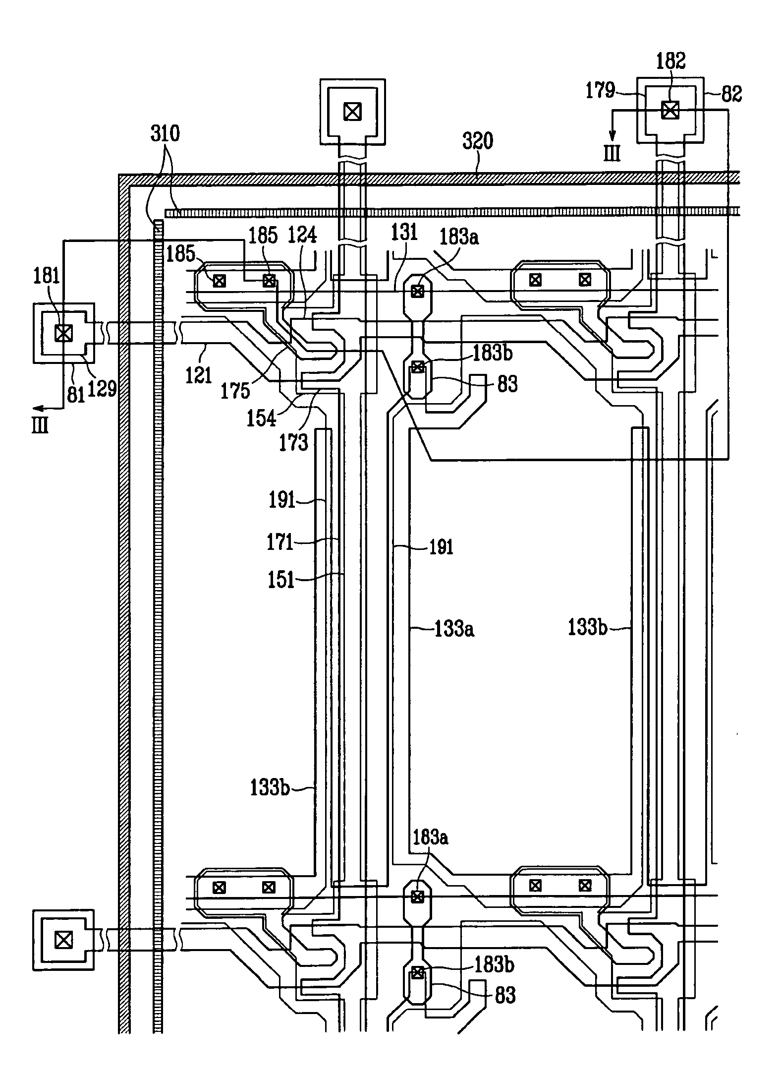
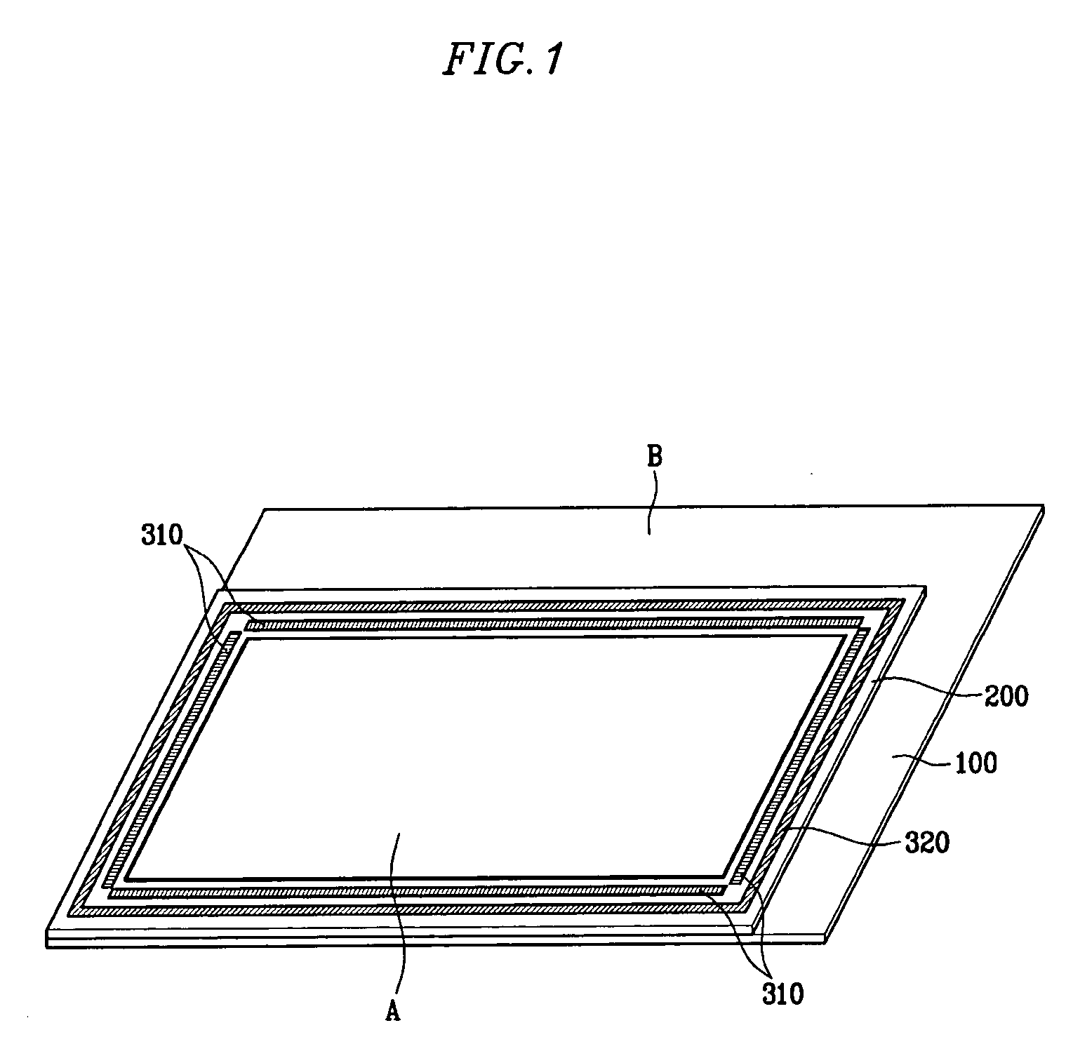
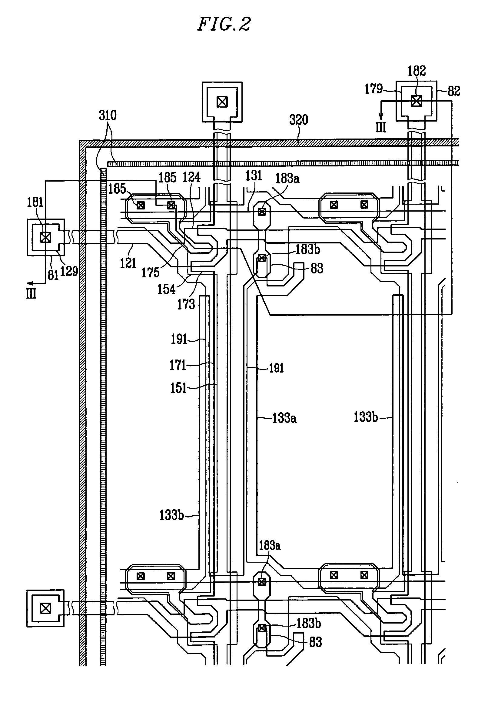
[0042]FIG. 1 is a perspective view of a liquid crystal display according to an embodiment of the present invention. FIG. 2 is a layout view of a liquid crystal display according to an embodiment of the present invention. FIG. 3 is a sectional view of an LCD taken along the line III-III in FIG. 2.

[0043] An LCD according to an embodiment of the present invention includes a TFT array panel 100, a common electrode panel 200 opposite to the TFT array panel 100, and an LC layer 3 having LC molecules disposed between the two panels 100 and 200. The LCD includes a display region A for dis...


PUM


Abstract

A liquid crystal display includes first and second panels facing each other, a sealant disposed between the first and second panels and formed along a perimeter of one of the two panels, a plurality of risings disposed on a same panel as the sealant and formed along a perimeter of a display region enclosed by the sealant, and a liquid crystal layer enclosed by the sealant and formed between the first and second panels.

Description

CROSS-REFERENCE TO RELATED APPLICATION [0001] This application claims priority to Korean Patent Application No. 10-2005-0081632 filed on Sep. 02, 2005, the contents of which are incorporated herein by reference in their entireties. BACKGROUND OF THE INVENTION [0002] (a) Technical Field [0003] The present disclosure relates to a liquid crystal display and a method for manufacturing the same, and more particularly to a liquid crystal display having a uniform cell gap and a method for manufacturing the same. [0004] (b) Discussion of the Related Art [0005] A liquid crystal display (LCD) is a widely-used flat panel display. The LCD may include two panels provided with field-generating electrodes such as pixel electrodes and a common electrode, and a liquid crystal (LC) layer interposed therebetween. The LCD displays images by applying voltages to the field-generating electrodes to generate an electric field in the LC layer, which determines orientations of LC molecules in the LC layer to...

Claims


Application Information

Patent Timeline
IPC IPC(8): G02F1/1339
CPCG02F1/1339
Inventor JANG, YANG-GYU
Owner SAMSUNG ELECTRONICS CO LTD
Why Eureka
Try Eureka