
Magnetized drill accessory for retention of objects

Active Publication Date: 2017-02-21
STEPHENSON JR SAMUEL S
View PDF4 Cites 1 Cited by
  • Summary
  • Abstract
  • Description
  • Claims
  • Application Information

AI Technical Summary

Benefits of technology

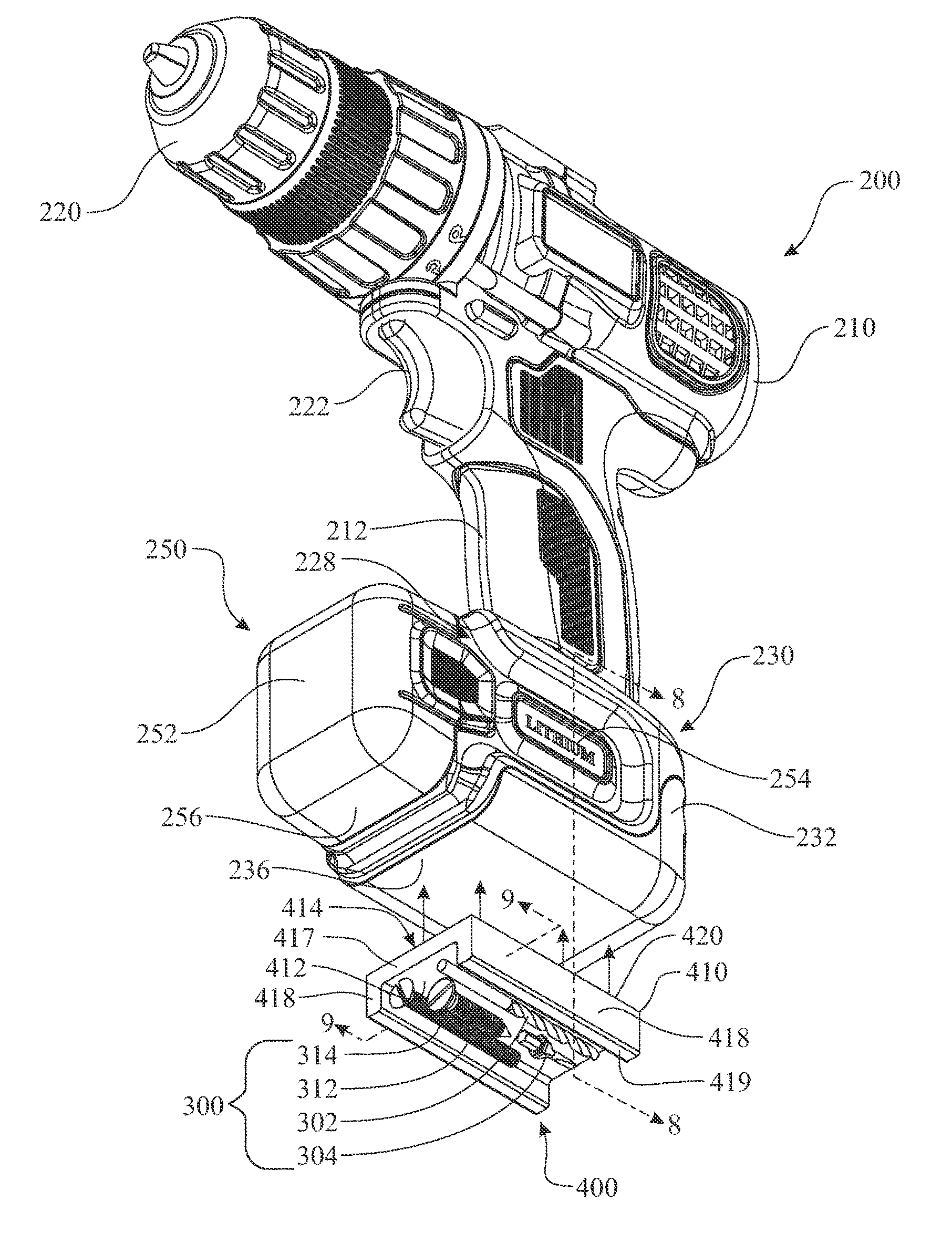
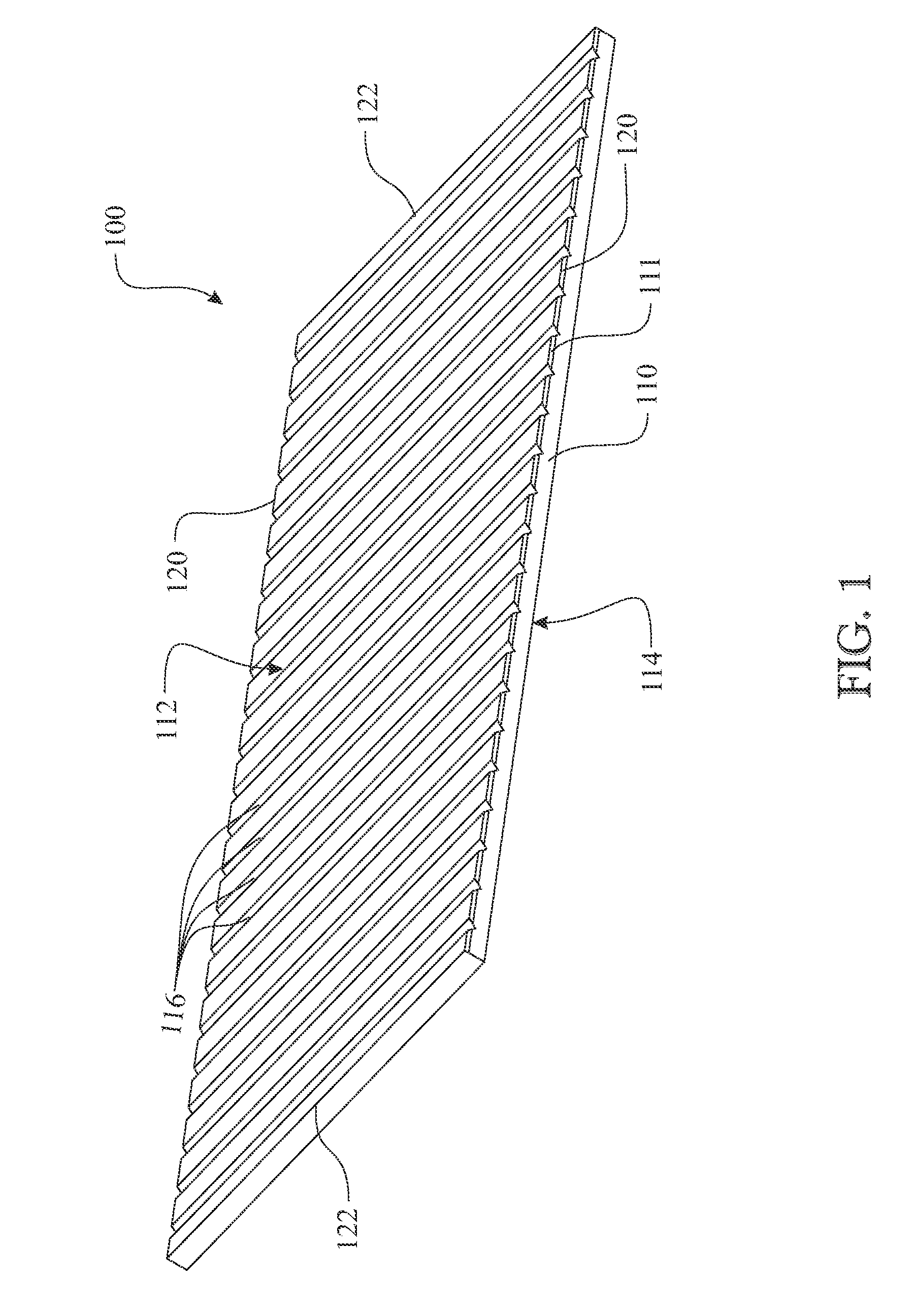
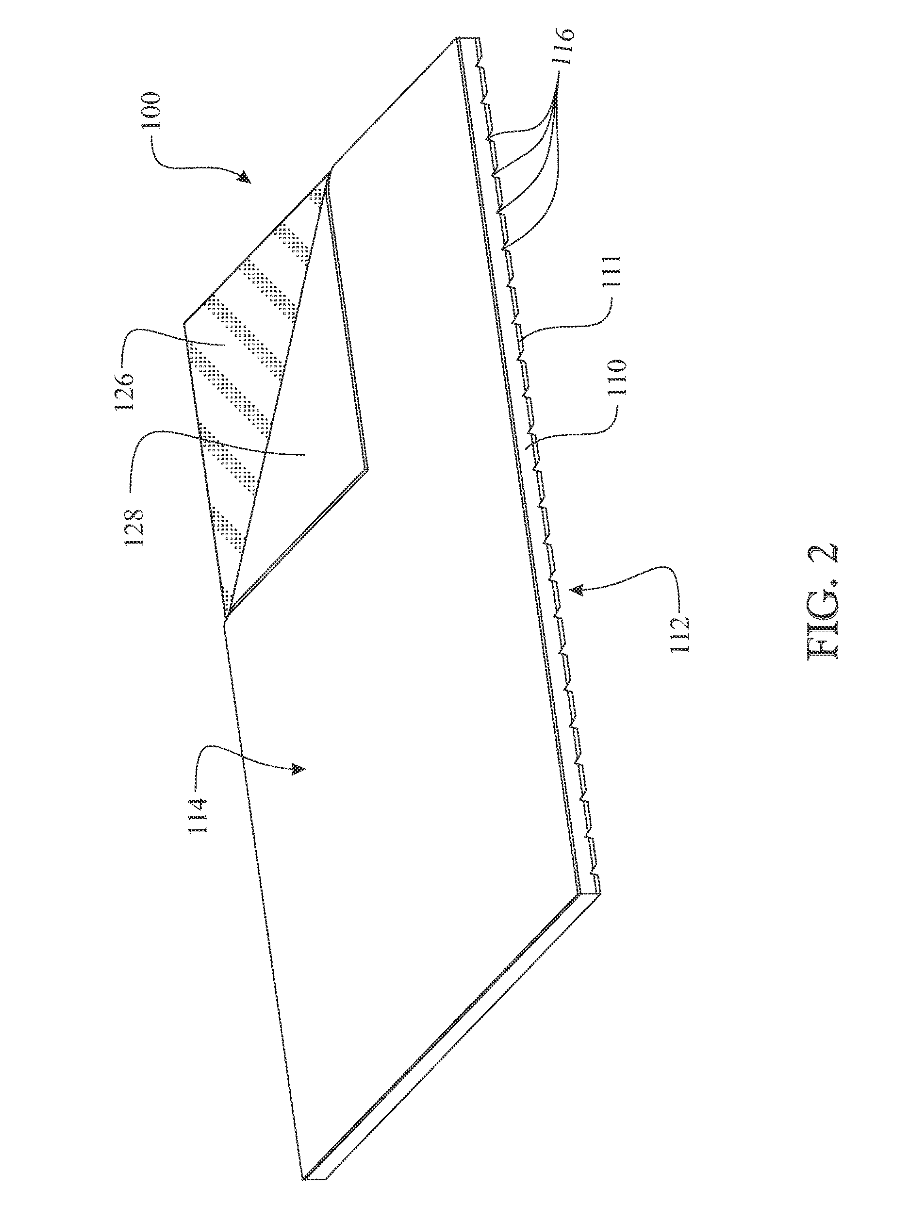
The present invention provides a method and apparatus for temporarily retaining objects while using a power tool, such as a portable power drill. The invention includes a magnetized object retention panel that can be attached to the drill or battery pack. The panel has a substrate with an exposed surface and an opposite attachment surface, with a magnetized material carried by the exposed surface. The panel can be attached to the drill housing or battery pack using adhesive or an adhesive carried by the attachment surface. The panel can also have grooves or a rounded or "U" shaped channel to facilitate the retention of objects. The technical effect of the invention is to provide a convenient way to temporarily retain objects while using a power tool.

Problems solved by technology

The problem is retaining the drill bit, the driver bit, and the series of screws throughout the various steps required for completing the task.
This takes additional time to retrieve the objects from within the pocket.
Sharp objects, such as screws, can be uncomfortable, or even cause injury to the individual, thus creating an undesirable scenario.
This solution introduces additional potential health risks including illness from ingesting bacteria or other contaminants residing on the surface of the objects or injury from swallowing the objects.
This solution is limited in that the retention element is designed to hold a specific object having a specific shape and size.
This solution fails to provide accommodations for retaining a broader selection of tools including drill bits, nut drivers, and the like; fasteners, such as screws, bolts, nuts, washers, and the like; and other objects that might be used during completion of a task.

Method used


Image

  • Magnetized drill accessory for retention of objects
  • Magnetized drill accessory for retention of objects
  • Magnetized drill accessory for retention of objects

Examples


Embodiment Construction

[0068]Detailed embodiments of the present invention are disclosed herein. It will be understood that the disclosed embodiments are merely exemplary of the invention that may be embodied in various and alternative forms. The figures are not necessarily to scale, and some features may be exaggerated or minimized to show details of particular embodiments, features, or elements. Specific structural and functional details, dimensions, or shapes disclosed herein are not limiting but serve as a basis for the claims and for teaching a person of ordinary skill in the art the described and claimed features of embodiments of the present invention. The following detailed description is merely exemplary in nature and is not intended to limit the described embodiments or the application and uses of the described embodiments. As used herein, the word “exemplary” or “illustrative” means “serving as an example, instance, or illustration.” Any implementation described herein as “exemplary” or “illust...


PUM

PropertyMeasurementUnit
Poweraaaaaaaaaa
Heightaaaaaaaaaa
Magnetismaaaaaaaaaa

Abstract

A magnetized material is affixed to an exterior of a drill housing of a portable power drill or a battery pack used for providing power to the portable power drill. The magnetized material is employed to retain magnetic objects. The magnetized material can be provided in a planar sheet or upon a three-dimensionally shaped form. In a sheet configuration, the magnetized object retention panel is defined by a magnetized surface and an opposite, attachment surface. A series of grooves can be formed within the magnetized material enabling conformation of the sheet to a non-planar surface on the drill or battery pack. The three-dimensionally shaped form can be provided as a channel having at least one channel sidewall extending generally perpendicular from an edge of a channel basewall terminating at a base surface. Inclusion of a pair of sidewalls provides a planar supporting surface for standing the drill upright.

Description

CROSS-REFERENCE TO RELATED APPLICATION[0001]This application is a Non-Provisional Application claiming the benefit of U.S. Provisional Patent Application Ser. No. 61 / 743,662, filed on Sep. 10, 2012, which is incorporated herein in its entirety.FIELD OF THE INVENTION[0002]The present invention relates to a drill accessory, and more particularly, a magnetized retention member that is adhesively attached to a portably power drill for temporarily retaining magnetic objects, such as drill bits, driver bits, screws, bolts, nuts, rivets, and the like.BACKGROUND OF THE INVENTION[0003]Drills are used for any of a variety of applications, including forming or enlarging holes through objects, forming countersinks, installing or securing threaded fasteners, or any other process utilizing a rotational motion. Because of the flexibility of the drill, there are many scenarios where the drill is used for multiple functions during the same time frame. It is common to need different objects to comple...

Claims


Application Information

Patent Timeline
IPC IPC(8): B23B45/00
CPCB23B45/003B65D85/24B65D85/00B25F5/02
Inventor STEPHENSON, JR., SAMUEL S.
Owner STEPHENSON JR SAMUEL S
Learn More