
Transmitter apparatus, communication system, and communication method

a technology of transmitter apparatus and communication system, applied in the field of transmitter apparatus, communication system and communication method, can solve the problems of difficult to accommodate variable rate users and complex process of equalizing them

Inactive Publication Date: 2007-03-08
INTELLIGENT COSMOS RES INST
View PDF10 Cites 56 Cited by
  • Summary
  • Abstract
  • Description
  • Claims
  • Application Information

AI Technical Summary

Benefits of technology

[0017] According to the invention of claim 1, since interleave-processed data obtained by performing specified rearrangement processes on frequency domain data which data symbols are converted into are generated in the interleaver, a signal transmission capable of providing a diversity effect without generating inter-user interference is possible.
[0042] Since this invention converts data symbols of spread signals to frequency domain signals and performs a rearrangement process (specified write process or read process) on the converted frequency domain signals by means of an interleaver and a de-interleaver, it is possible to obtain a frequency diversity effect while orthogonalizing transmission signals of many users in frequency.

Problems solved by technology

However, the above-mentioned transmission techniques have a problem that it is difficult to accommodate variable rate users due to performing FDMA communication by the operation of repeating a data block and giving a frequency offset.
And they have also a problem that in case that there are a very large number of paths being different in delay time in propagation paths, a process of equalizing them is very complicated since a time domain equalization process is performed using a least error estimation or a matching filter detection.

Method used


Image

  • Transmitter apparatus, communication system, and communication method
  • Transmitter apparatus, communication system, and communication method
  • Transmitter apparatus, communication system, and communication method

Examples


embodiment 1

[0074] (Application to DS-CDMA Transmission)

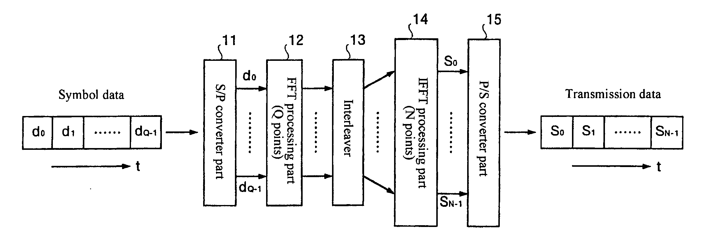
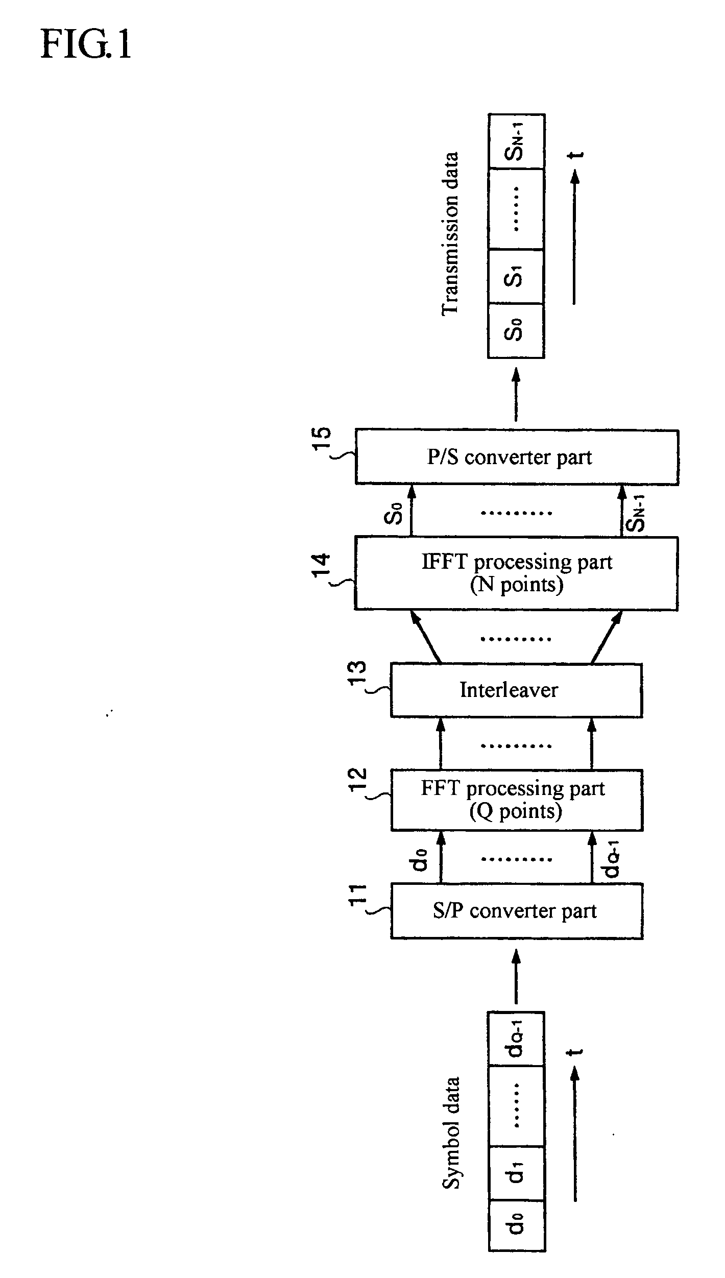
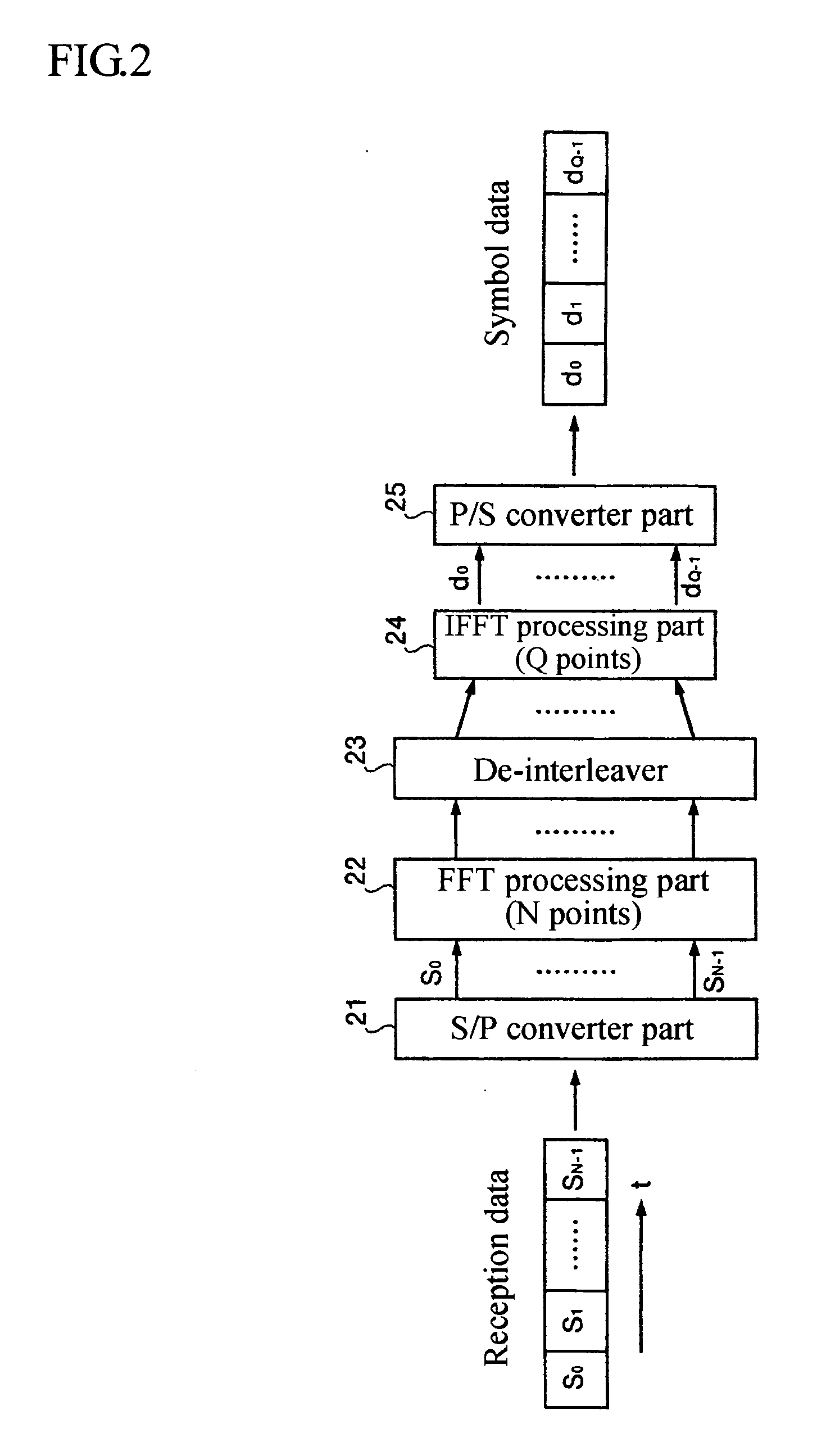
[0075]FIG. 1 is a transmission system block diagram showing the composition of a main part of a transmitter apparatus of embodiment 1. In the transmission system shown in the same figure, symbol data (d0, d1, . . . , dQ-1) consisting of a sequence of Q symbols on which a specified modulation is performed for DS-CDMA transmission are inputted. Expression “symbol data” is the same as “data symbol” used in claims and means for solving the problems, but this expression is used for keeping the unity of expression pertaining to other outputs. And the transmission system shown in the same figure is provided with an S / P (serial to parallel) converter part 11 for converting symbol data (di) serial-transmitted to parallel data, an FFT processing part 12 for performing fast Fourier transform (FFT: Fast Fourier Transform) processes on the parallel data, an interleaver 13 for performing an interleave process (transmission system write process / transmis...

embodiment 2

[0099]FIG. 9 is a transmission system block diagram showing the composition of a main part of a transmitter apparatus of embodiment 2 and FIG. 10 is a reception system block diagram showing the composition of a main part of a receiver apparatus of embodiment 2. Although an example of application of an interleave process and de-interleave process being a feature of this invention to a DS-CDMA transmission system has been described in embodiment 1 described above, an example of application of them to an OFDM transmission system is described in embodiment 2.

[0100] A transmission system shown in FIG. 9 is provided with an S / P converter part 31 for converting OFDM symbol data (a0, a1, . . . , aQ-1) having a spectrum for OFDM transmission as shown in the same figure to parallel data, an interleaver 32 for performing interleave processes similar to embodiment 1 on the basis of these parallel data, an IFFT processing part 33 for performing inverse fast Fourier transform processes on output...

embodiment 3

[0107]FIG. 11 is a transmission system block diagram showing the composition of a main part of a transmitter apparatus of embodiment 3. FIG. 12 is a reception system block diagram showing the composition of a main part of a receiver apparatus of embodiment 3. Although an example of application of an interleave process and de-interleave process being a feature of this invention to a DS-CDMA transmission system or an OFDM transmission system has been described in the above-mentioned embodiments 1 and 2, an example of application of them to an MC-CDMA transmission system is described in embodiment 3.

[0108] A transmission system shown in FIG. 11 is provided with an S / P converter part 51 for converting symbol data (b0, b1, . . . , bQ-1) for MC-CDMA transmission to parallel data, duplicator parts 521 to 52Q for respectively duplicating each piece of these parallel data by a specified number of pieces, spreading processing parts 531 to 53Q for generating spread signals on the basis of sig...


PUM


Abstract

A communication technology for allowing a mobile communication system to accommodate variable rate users, while obtaining a frequency diversity effect. A transmitter apparatus using, for transmission, transmission signals produced based on data symbols of a predetermined transmission method, comprising an FFT processing part for converting the data symbols to frequency domain data; an interleaver for sorting the frequency domain data; and an IFFT processing part for converting the sorted frequency domain data to a time domain signal; wherein the FFT processing part subjects Q received data symbols to Q-point FFT processing, the interleaver produces N data from Q data outputted from the FFT processing part (where N>Q), and the IFFT processing part subjects the N data outputted from the interleaver to N-point IFFT processing.

Description

TECHNICAL FIELD [0001] This invention relates to a transmitter apparatus, a communication system and a communication method, and more particularly to a transmitter apparatus preferable for mobile communications, a communication system provided with this transmitter apparatus and a communication method preferable for mobile communications. BACKGROUND ART [0002] In recent times, the development of a mobile communication industry represented by mobile phones is making rapid progress. With this rapid progress, various services by means of mobile communications are also diversified. Particularly, future needs for mobile communications necessarily move to multimedia communications for integrating and communicating various kinds of data including not only voices but also texts, images and the like, and the combination of those needs and the increase of amount of transmitted information further expected in the future demands the increase of signal transmission speed. [0003] On the other han...

Claims


Application Information

Patent Timeline
Patent Type & Authority Applications(United States)
IPC IPC(8): H04K1/10H04L1/00H04J11/00H04L27/26
CPCH04L1/0071H04L27/2602H04L1/04H04L1/0083H04L27/2636
Inventor ADACHI, FUMIYUKI
Owner INTELLIGENT COSMOS RES INST
Learn More