Connector with reference conductor contact

a technology of reference conductor and connector, applied in the direction of connection contact member material, two-part coupling device, coupling device connection, etc., can solve the problems of electrical noise generation in the connector, the electronic system generally becomes smaller, and the connection contact material is more flexible and flexibl

Active Publication Date: 2007-03-08
AMPHENOL CORP
View PDF6 Cites 111 Cited by
  • Summary
  • Abstract
  • Description
  • Claims
  • Application Information

AI Technical Summary

Problems solved by technology

Electronic systems have generally become smaller, faster and functionally more complex.
As connector density signal frequencies increase, there is a greater possibility of electrical noise being generated in the connector as a result of reflections caused by impedance mismatch or cross-talk between signal conductors.

Method used


Image

  • Connector with reference conductor contact
  • Connector with reference conductor contact
  • Connector with reference conductor contact

Examples


Embodiment Construction

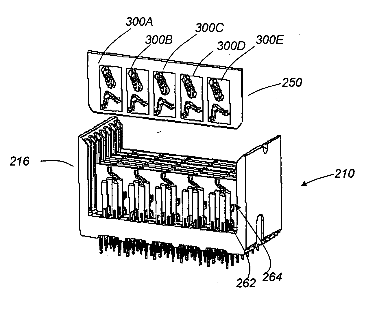
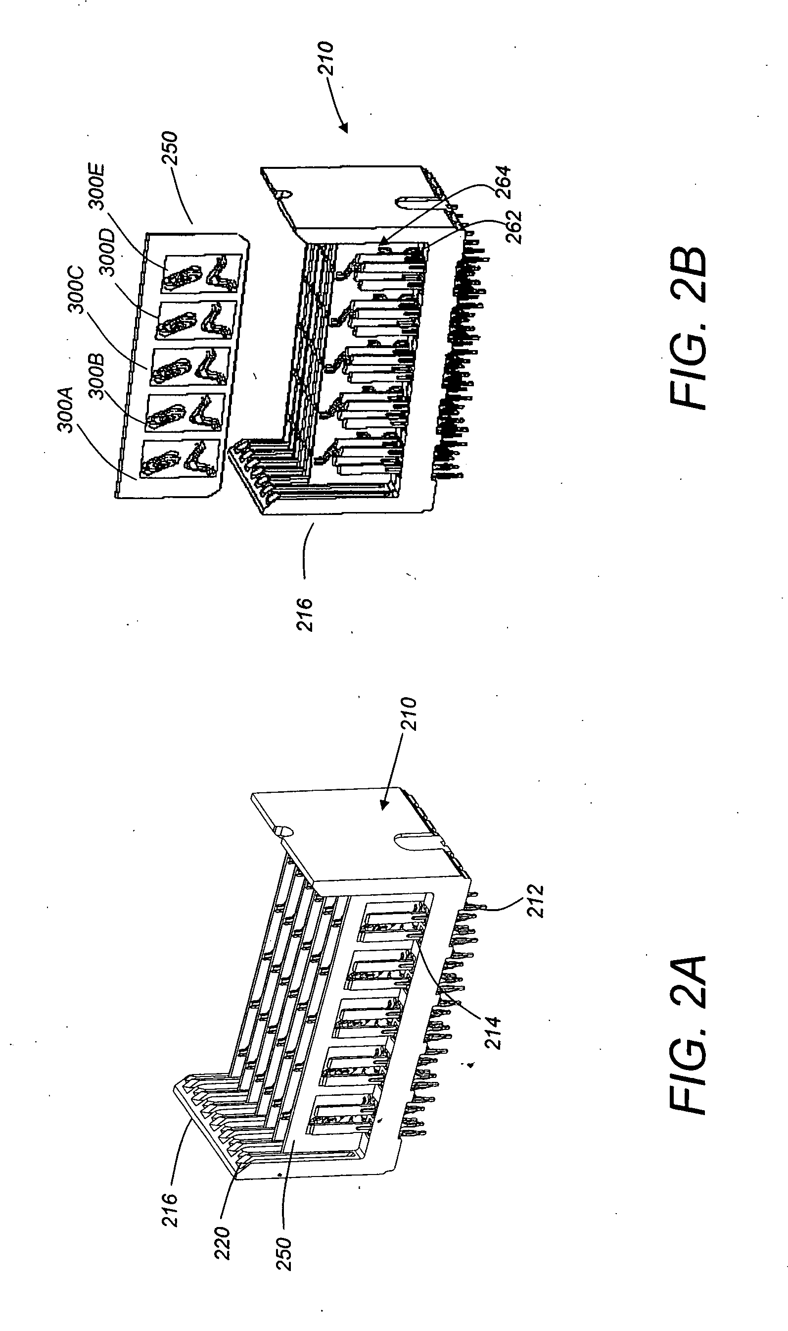
[0022] An improved interconnection system is provided with a reference conductor having a contact providing two or more points of contact when mated. Such a contact provides a low impedance interconnection and may be constructed to provide other advantages, such as a desirable ground current flow pattern and reduced ringing in connectors having advance ground mating.

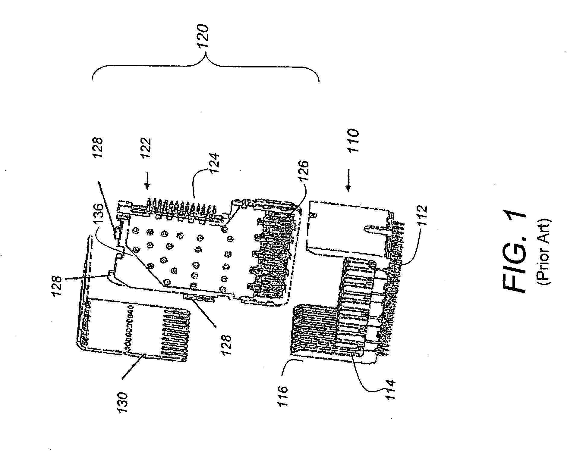
[0023] The invention is illustrated in connection with a backplane-daughter card interconnection system. However, the invention is not limited in its application to the details of construction and the arrangement of components set forth in the following description or illustrated in the drawings. The invention is capable of other embodiments and of being practiced or of being carried out in various ways. Also, the phraseology and terminology used herein is for the purpose of description and should not be regarded as limiting. The use of “including,”“comprising,” or “having,”“containing,”“involving,” and variations there...


PUM


Abstract

An electrical connector with a reference contact for improved shielding. The contact provides multiple points of contact between members in the ground structure of two mating connectors. The points of contact are arranged to provide desirable current flow in the signal paths and ground structures of the connectors. The contact is stamped from a shield plate and has multiple elongated members that provide spring force for adequate electrical connection. The elongated members are curved to position the points of contact with the desired orientation. Such a contact structure may be used alone or in combination with other compliant structures providing further points of contact.

Description

BACKGROUND OF INVENTION [0001] 1. Field of Invention [0002] This invention relates generally to electrical interconnection systems and more specifically to electrical interconnection systems, such as high speed electrical connectors, with improved signal integrity. [0003] 2. Discussion of Related Art [0004] Electrical connectors are used in many electronic systems. Electrical connectors are often used to make connections between printed circuit boards (“PCBs”) that allow separate PCBs to be easily assembled or removed from an electronic system. Assembling an electronic system on several PCBs that are then connected to one another by electrical connectors is generally easier and more cost effective than manufacturing the entire system on a single PCB. [0005] Electronic systems have generally become smaller, faster and functionally more complex. These changes mean that the number of circuits in a given area of an electronic system, along with the frequencies at which those circuits op...

Claims


Application Information

Patent Timeline
Patent Type & Authority Applications(United States)
IPC IPC(8): H01R13/648
CPCH01R23/688H01R13/6587H01R12/00
Inventor DO, TRENT K.COHEN, THOMAS S.
Owner AMPHENOL CORP
Why Eureka
Try Eureka