Portable Religious Shrine

a portable, religious technology, applied in dolls, show cards, advertising, etc., can solve the problems of not being able to travel to these places of worship, not being able to be used by two or more people, and being unable to meet the needs of worshipers,

Inactive Publication Date: 2007-03-08
MJDC
View PDF42 Cites 5 Cited by
  • Summary
  • Abstract
  • Description
  • Claims
  • Application Information

AI Technical Summary

Benefits of technology

[0052] The advantages of the portable religious shrine of the present invention are numerous. First, the portable religious shrine of the present invention can be made at low cost so that the portable religious shrine can be an inexpensive and readily affordable item to a large number of users. The portable religious shrine is constructed for quick and easy assembly and disassembly. Second, the portable religious shrine of the present invention provides an immediate spiritual ambiance not provided by the conventional arts. Third, the portable religious shrine could be utilized as a temporary or permanent place of worship.

Problems solved by technology

However, in some situations, it is not possible for worshipers to travel to these places of worship.
First, the portable prayer altar is suitable only for a single user and cannot be used by two or more people at the same time, such as a family or a gathering of people.
Second, the padded kneeling mechanism requires the use of an air compressor and an air tank which increases the complexity and cost of the prayer structure.
The portable religious shrine of Keshishian is of a small size and thus has limited applications.
The small Buddhist shrines are generally of a small size and thus not conducive for use by a large group of worshipers.
Also, because of their small sizes and appearance as a furniture piece, these shrines do not provide a general ambience for the rooms in which the shrines are placed.
This type of portable shrine is used as a carrier of other objects and does not itself provide a religious ambience for religious observance.
This type of portable shrine is used only for ceremonial purposes and is not suitable for indoor use.

Method used


Image

  • Portable Religious Shrine
  • Portable Religious Shrine
  • Portable Religious Shrine

Examples


second embodiment

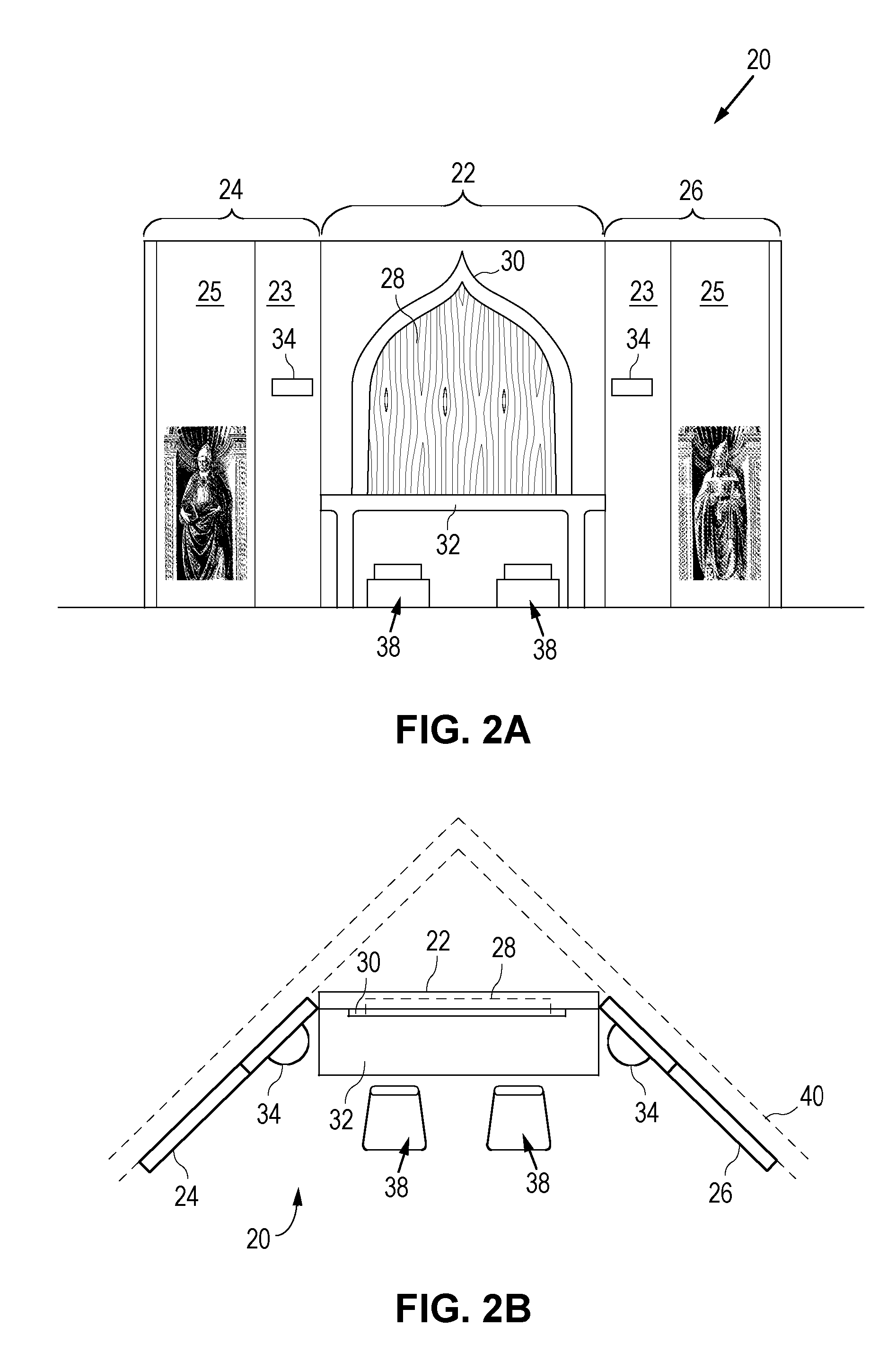
[0033]FIG. 2A is a front view of and FIG. 2B is a top view of a portable religious shrine according to the present invention. Referring to FIGS. 2A and 2B, portable religious shrine 20 includes a center wall panel 22, a left wall panel 24 and a right wall panel 26. The left and right wall panels 24, 26 are angled with respect to the center wall panel 22 so that portable religious shrine 20 can be set up against the corner of a room 40. In the present embodiment, the height of portable religious shrine 20 extends to nearly the full height of room 40 in which the shrine is situated. When room 40 has an 8-foot ceiling, portable religious shrine 20 has a height of about 8 feet. Also, in the present embodiment, each of wall panels 24, 26 includes a first wall panel portion 23 and a second wall panel portion 25. The first wall panel portion 23 and the second wall panel portion 25 are connected to form a respective wall panel. The use of separate wall panel portions to form a wall panel al...

third embodiment

[0040]FIG. 3 is a perspective view of a portable religious shrine according to the present invention. FIG. 4 is a top view of the portable religious shrine of FIG. 3. Referring to FIGS. 3 and 4, a portable religious shrine 100 is formed in the same manner as described above with reference to FIGS. 2A and 2B. However, in the present embodiment, portable religious shrine 100 includes a roof panel 150 and a floor panel 160. Each of roof panel 150 and floor panel 160 is optional and may be added to the portable shrine structure when desired.

[0041] In the present embodiment, roof panel 150 is made up of light weight plastic and includes visual 3-dimensional photographic images depicting the ceiling of the desired place of worship so that the roof panel 150 and the wall panels 112, 114 and 116 together form a unified image depicting the desired place of worship. For example, the bottom surface of the roof panel, i.e. the ceiling of the portable religious shrine 100, can be overlaid with a...

fourth embodiment

[0043]FIG. 5A is a front view of and FIG. 5B is a top view of a portable religious shrine according to the present invention. FIG. 6 is a perspective view of the portable religious shrine of FIGS. 5A and 5B. Referring to FIGS. 5A, 5B and 6, a portable religious shrine 200 includes a center wall panel 222, a left wall panel 224 and a right wall panel 226. In the embodiments shown above, the portable religious shrine of the present invention is set up against the corner of a room. In the present embodiment, portable religious shrine 200 is constructed so that the center wall panel 222 is set up against the wall 240 of a room or a hallway. The center wall panel 222 of portable religious shrine 200 has a greater width than the two side panels 224 and 226. A table 232 attached to the center wall penal 222 extends to the side panels 224 and 226. In the present embodiment, each of the left and right wall panels 224, 226 is formed by a single wall panel portion and includes a half-round she...


PUM


Abstract

A religious display structure includes two or more removably interconnected wall panels forming a freestanding enclosure for accommodating one or more users. Each wall panel includes a visual 3-dimensional photographic image formed on the front surface of the wall panel where the images on all of the wall panels form religious scenery depicting a place of worship for the one or more users. In one embodiment, the religious scenery is selected from a church, a chapel, a temple, or a synagogue. The enclosure formed by the wall panels can be a partial enclosure or a complete enclosure forming an enclosed space. In one embodiment, the religious display structure is made of plastic and the structure is made for easy assembly and disassembly. The religious display structure can be used in various settings, such as a home or an office, to provide a place of worship for the user.

Description

[0001] CROSS-REFERENCE TO RELATED APPLICATION [0002] This application claims the benefit of U.S. Provisional Patent Application Ser. No. 60 / 713,647, filed on Sep. 2, 2005, having the same inventorship hereof, which application is incorporated herein by reference in its entirety.FIELD OF THE INVENTION [0003] This invention relates to a portable religious shrine for use in a home, a commercial building or as part of a landscaped area of a single family dwelling, and more particularly to a portable religious shrine that can be set up to provide the desired ambiance for religious observance. DESCRIPTION OF THE RELATED ART [0004] Places of worship, such as a church, a chapel, a temple or a synagogue, are constructed to provide an ambiance suitable for religious observance. Worshipers travel from their homes to these places of worship to attend religious ceremonies or to pray privately. However, in some situations, it is not possible for worshipers to travel to these places of worship. Al...

Claims


Application Information

Patent Timeline
Patent Type & Authority Applications(United States)
IPC IPC(8): A63H3/52
CPCG09F19/00G09F1/08
Inventor PINTO, MANUEL P.
Owner MJDC
Why Eureka
Try Eureka