
Apparatus for supplying and press-fitting part to work

a technology for supplying and pressing parts, applied in the direction of metal working apparatus, metal-working machine components, manufacturing tools, etc., can solve the problem of prone to increase the cost of the whole system, and achieve the effect of improving the assembling accuracy

Inactive Publication Date: 2007-03-15
HONDA MOTOR CO LTD +1
View PDF23 Cites 32 Cited by
  • Summary
  • Abstract
  • Description
  • Claims
  • Application Information

AI Technical Summary

Benefits of technology

[0011] In accordance with the part supplying and press-fitting apparatus, because the chuck device preferably grips a part with placing it on the placement table face, a stability of the part grip increases and the detection device comes off with a simple structure; thus the apparatus becomes economical one.
[0013] In accordance with the part supplying and press-fitting apparatus, by preferably swiveling the arm portion, it is possible to place a part on the placement table face without making the part, which is supplied from the part feeder side intervene, with a grip portion of the chuck device.
[0017] In accordance with the part supplying and press-fitting apparatus, it is possible to preferably improve an assembling accuracy in an assembling process of a connecting rod and a bush.

Problems solved by technology

In addition, in the conventional method of supplying and press-fitting the bush P, because an optical sensor such as a laser sensor is used as a sensor for detecting the cutout Pc, there also exists a problem that a whole system is apt to become expensive.

Method used


Image

  • Apparatus for supplying and press-fitting part to work
  • Apparatus for supplying and press-fitting part to work
  • Apparatus for supplying and press-fitting part to work

Examples


Embodiment Construction

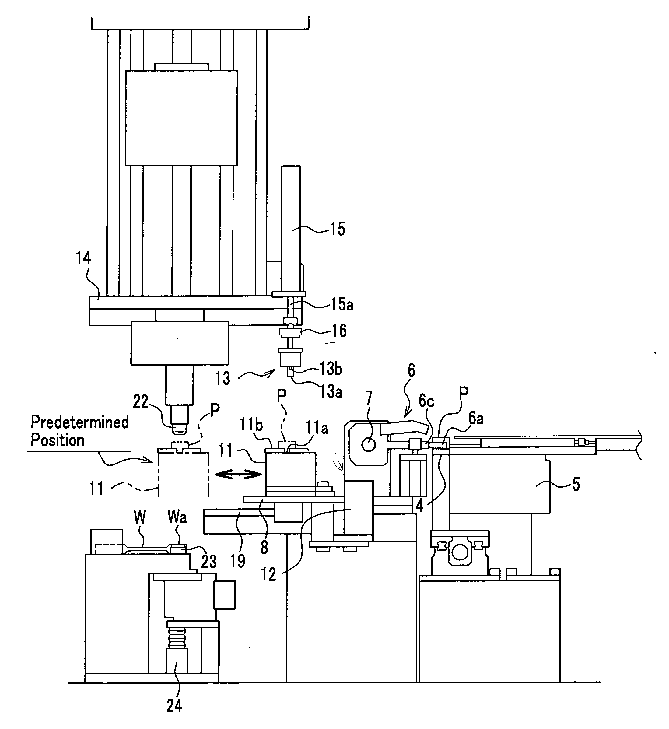
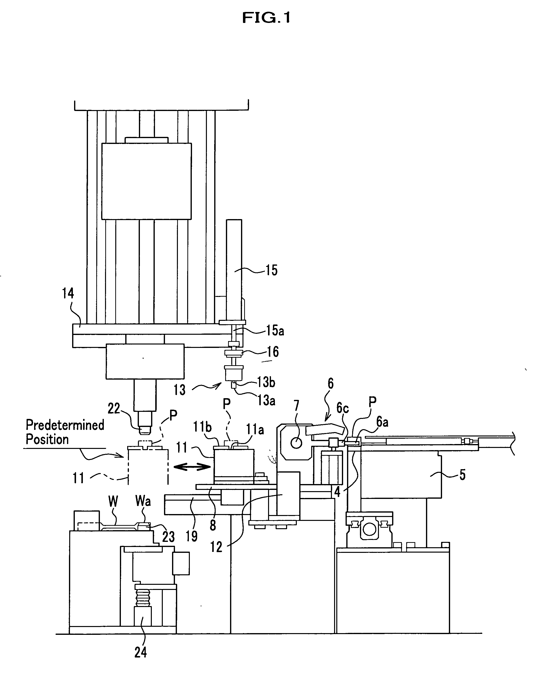
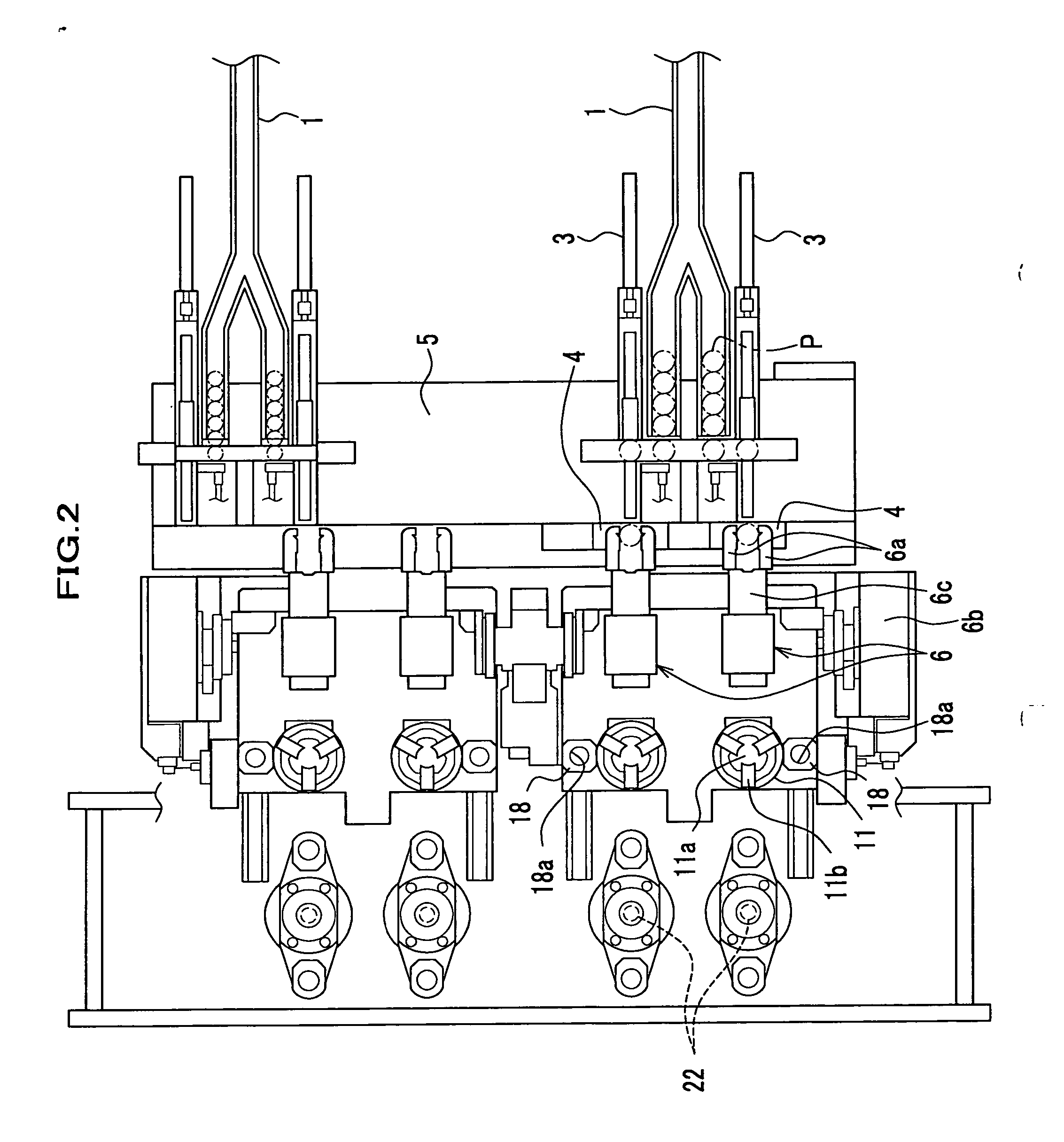
[0027] Here will be described a part supplying and press-fitting apparatus in a case of assuming a part and a work to be respectively the bush P and the connecting rod W shown in FIG. 8. FIGS. 1 to 3 are respectively side, plan, and front illustration drawings of the part supplying and press-fitting apparatus related to the present invention.

[0028] In FIG. 2 symbols 1 respectively show supply lanes of bushes P linked to a part feeder not shown. Each bush P is conveyed in a single row in each of the supply lanes 1, making its hole direction a perpendicular direction. A downstream side of the supply lane 1 is forked into two, and the bush P is appropriately distributed to either of the two lanes. Receiving a check of a presence or absence, the bush P discharged from a downstream end of each of the two-forked lanes of the supply lane 1 is then conveyed outward a left or right direction (up or down direction in FIG. 2), next contacted with a pressure by a cylinder 3, and sent into a di...


PUM

PropertyMeasurementUnit
pressureaaaaaaaaaa
positional displacementaaaaaaaaaa
rotationaaaaaaaaaa

Abstract

This part supplying and press-fitting apparatus for supplying an annular part to a predetermined position and press-fitting the part into a press-fit hole of a work in a state of being positioned in a circumferential direction includes a grip device for gripping the part; a rotation device for rotating the grip device around a hole axis of the part in a state of having gripped the part; a detection device for detecting the detected portion of the part being rotated by the rotation device; a stop device for stopping the rotation of the grip device when the detected portion is detected; a move device for moving the grip device stopped by the stop device to the predetermined position; and a press-fit head configured to descend to the predetermined position and to press-fit the part into a press-fit hole of the work.

Description

BACKGROUND OF THE INVENTION [0001] 1. Field of the Invention [0002] The present invention relates to an apparatus for supplying and press-fitting a part to a work. [0003] 2. Description of the Related Art [0004]FIG. 8 is an appearance perspective view around a smaller end of a connecting rod W, which is a component of an engine of such a vehicle, and a bush P press-fitted into the smaller end. FIG. 9 shows a section of a main portion of the bush P. On an inner peripheral face of the bush P is formed an oil groove Pa. In press-fitting such the bush P into a press-fit hole Wa of the connecting rod W, it is requested to strictly positioning a position and direction of the oil groove Pa and thereafter to press-fit the bush P into the hole Wa. In another process after the press-fit, an oil hole is integrally drilled that fronts the oil groove Pa of the bush P from an outside face of the smaller end of the connecting rod W. [0005] A conventional method of supplying and press-fitting the b...

Claims


Application Information

Patent Timeline
Patent Type & Authority Applications(United States)
IPC IPC(8): B23P21/00
CPCB23P19/007B23P19/02Y10T29/53078Y10T29/49895Y10T29/53396Y10T29/53978Y10T29/53387
Inventor HANAOKA, TADASHIMARUYAMA, SHUICHIHIGUMA, TOSHIROUIWAI, YOSHIHARU
Owner HONDA MOTOR CO LTD
Learn More