Weeping system for window screen corner keys

a weeping system and corner key technology, applied in the field of corner key weeping system, can solve the problems of unfinished appearance, unattractive and unfinished appearance, and adversely affect the window or door assembly and/or the underlying building structure,

Inactive Publication Date: 2007-03-15
SIMONTON BUILDING PRODS
View PDF10 Cites 17 Cited by
  • Summary
  • Abstract
  • Description
  • Claims
  • Application Information

AI Technical Summary

Benefits of technology

[0007] The invention is an improved corner key with weeping holes, or openings, situated on at least one of the legs of the corner key. The openings are strategically positioned on the leg such that, when the corner key is included in a screen frame, the water may pass through the openings while the entire bottom section of the screen rests flush a...

Problems solved by technology

One problem with having a screen on the outside of a window or door is that water can collect between the screen and the window or door, and ad...

Method used


Image

  • Weeping system for window screen corner keys
  • Weeping system for window screen corner keys
  • Weeping system for window screen corner keys

Examples


Embodiment Construction

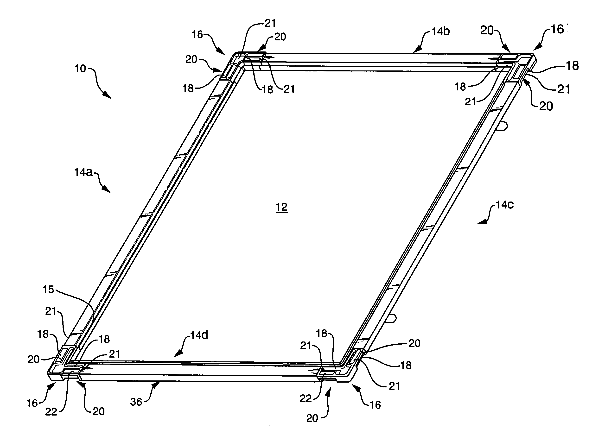
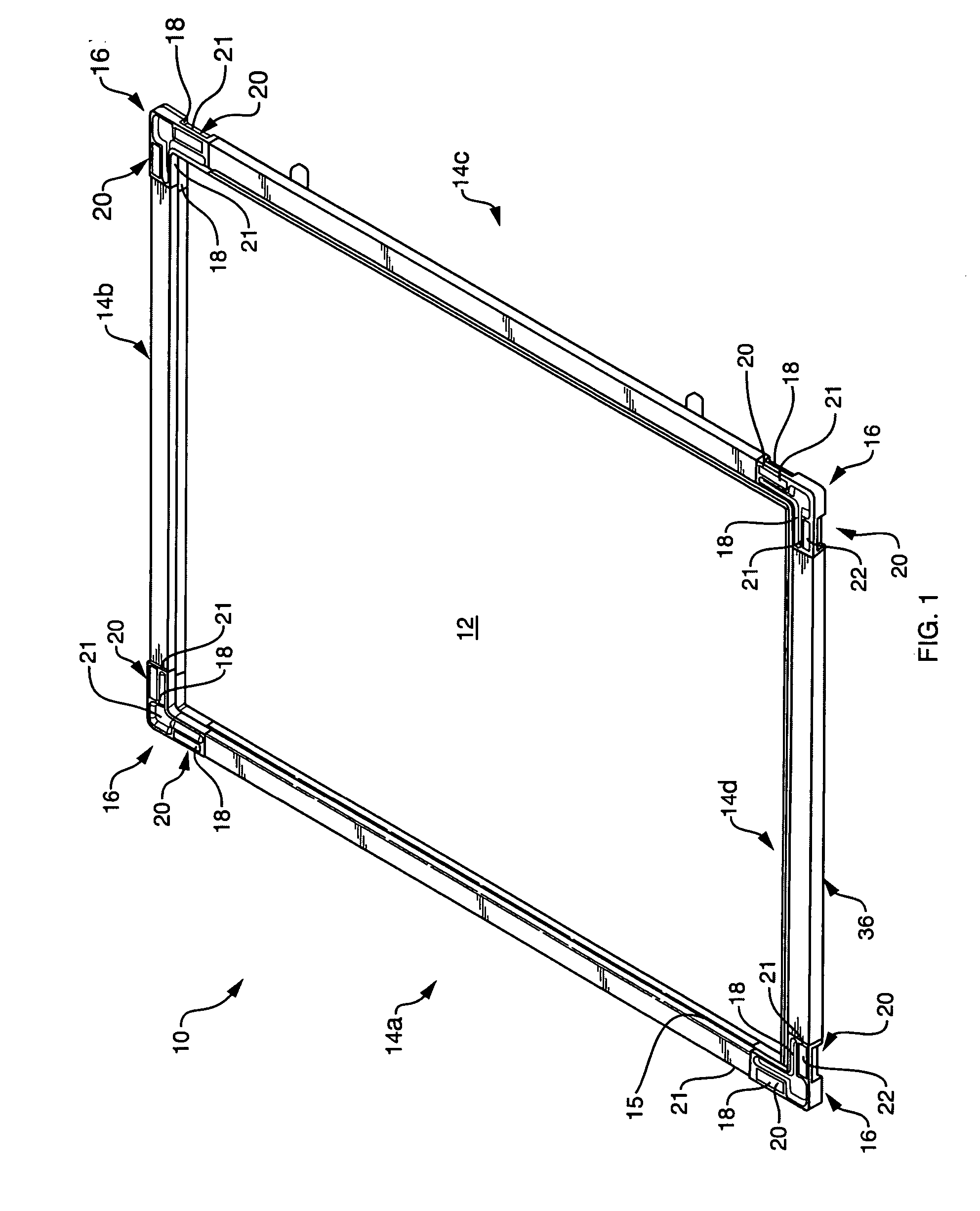
[0015]FIG. 1 depicts an exterior side of a screen 10 that is constructed in accordance with a first embodiment of the invention. The screen 10 includes a frame 14 that consists of four frame segments 14a-d and interconnecting corner keys 16. The frame 10 supports screening 12 that mounts on the frame in a conventional manner, utilizing troughs 15 on the various frame segments.

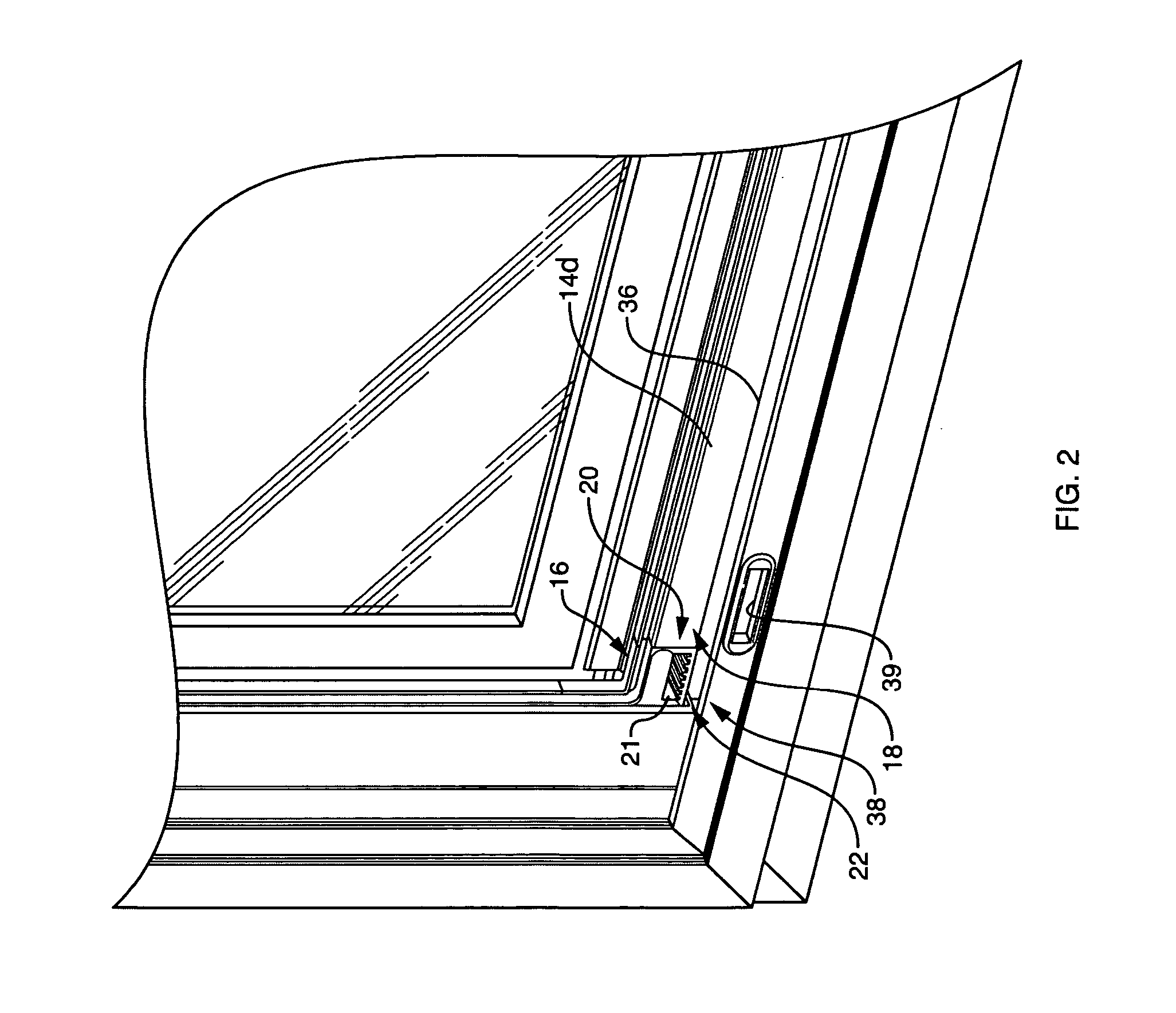
[0016] Referring also to FIG. 2, at least one of the corner keys 16 contains a plurality of weeping holes, or openings 18, to allow water to drain through the corner key. The openings, which are formed in an inner wall 21 of an indent 20, are strategically positioned such that a bottom edge 22 of the corner key remains intact. Accordingly, the entire bottom edge 36 of the screen 10, which includes the frame segment 14d and the two associated corner keys 16, sits flush on a sill 38 when the screen is in place. The bottom edge 36 of the screen, which includes the bottom edges 22 of the two corner keys, prevents ...


PUM


Abstract

A corner key with a first and second leg each with an upper and lower portion. The corner key including a plurality of openings, formed in an indent on the upper portion of at least one of the first and second legs, for weeping water through the corner key.

Description

BACKGROUND OF THE INVENTION [0001] 1. Field of the Invention [0002] This invention relates generally to a corner key weeping system to be used with a window, patio door and sliding door screens. [0003] 2. Background Information [0004] A window or door screen consists of mesh or screening supported by a lightweight rectangular frame. The frame includes four essentially straight segments, i.e., the top, the bottom, and the left and right sides, which are connected at adjacent ends to form the corners of the frame. The ends are either cut at forty-five degree angles and connected directly together to form ninety-degree corners, or the ends are cut to mate with “corner keys,” which are corner shaped connectors. Each corner key basically consists of two legs with their adjacent ends joined at a ninety-degree angle to form a corner. The free ends of the legs fit within or over the adjacent end of the frame segments, to connect these segments via the corner, at a ninety-degree angle. [0005...

Claims


Application Information

Patent Timeline
IPC IPC(8): A47G5/00
CPCE06B9/52
Inventor BROOKER, STEVEN F.KIRK, TIMOTHY S.HECK, EDWARDSTROUP, JULIA
Owner SIMONTON BUILDING PRODS
Why Eureka
Try Eureka