
Method and arrangement for adjusting an output impedance of a power amplifier

a power amplifier and output impedance technology, applied in the field of communication devices, can solve the problems of complex mathematical operations needed to solve the values of cb>1/b> and cb>2/b>, and the complexity of mathematical operations associated with impedance matching is an awkward issue, and each component means costs, so as to reduce the cost of a power amplifier system whose output impedance is to be matched with a load impedance, the effect of power loss

Active Publication Date: 2007-03-15
NOKIA TECHNOLOGLES OY
View PDF7 Cites 25 Cited by
  • Summary
  • Abstract
  • Description
  • Claims
  • Application Information

AI Technical Summary

Benefits of technology

The present invention provides a transmitter with a power amplifier that can match its output impedance with the load impedance, thus eliminating or reducing the limitations and drawbacks of prior art solutions. This is achieved by adjusting the operating point of the output stage transistor of the power amplifier to match the real part of the output impedance with the real part of the load impedance. This solution reduces the complexity of mathematical operations associated with impedance matching, reduces power losses, space requirements, and costs of the system. A mobile communication device comprising this transmitter is also provided. A set of integrated circuits for constructing this transmitter is also provided. A method for matching the output impedance of the power amplifier with the load impedance is also provided.

Problems solved by technology

The mathematical operations needed for solving the values of C1 and C2 are, however, quite complex.
Each component means costs, a need for space, and power losses.
The complexity of mathematical operations associated with impedance matching is an awkward issue especially when impedance matching is intended to be performed at successive time instants with a short interim time period in order to be able to follow changing conditions, e.g. temporal variation of an impedance of an antenna of an mobile communication device.
The processing capacity needed for the mathematics means costs, a need for space, and a need for power.

Method used


Image

  • Method and arrangement for adjusting an output impedance of a power amplifier
  • Method and arrangement for adjusting an output impedance of a power amplifier
  • Method and arrangement for adjusting an output impedance of a power amplifier

Examples


Embodiment Construction

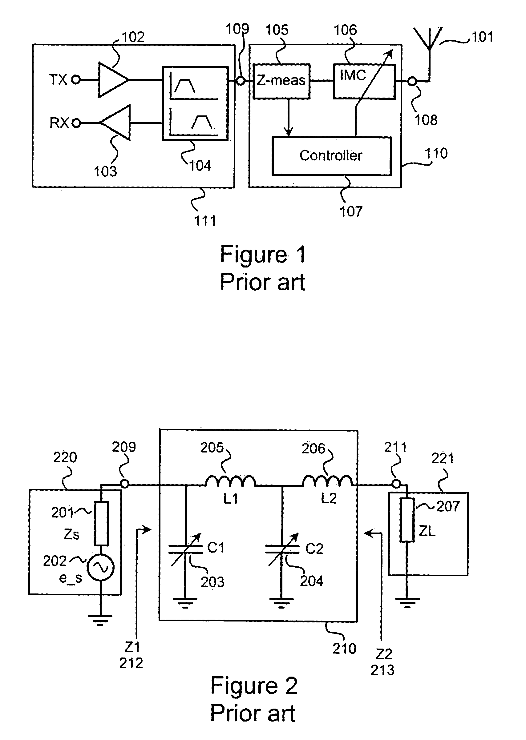
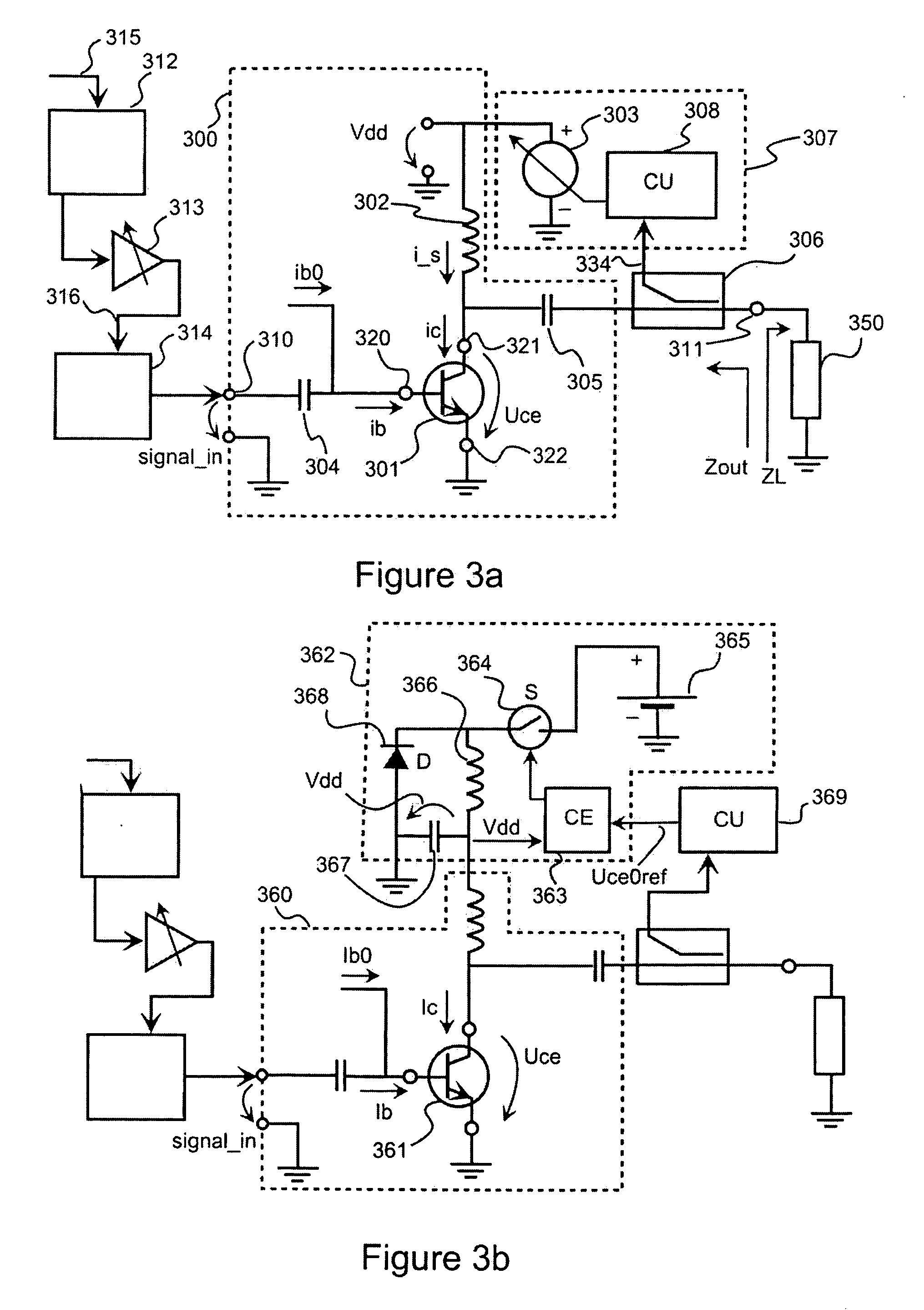
[0044]FIGS. 1-2 have been explained above in the description of the prior art.

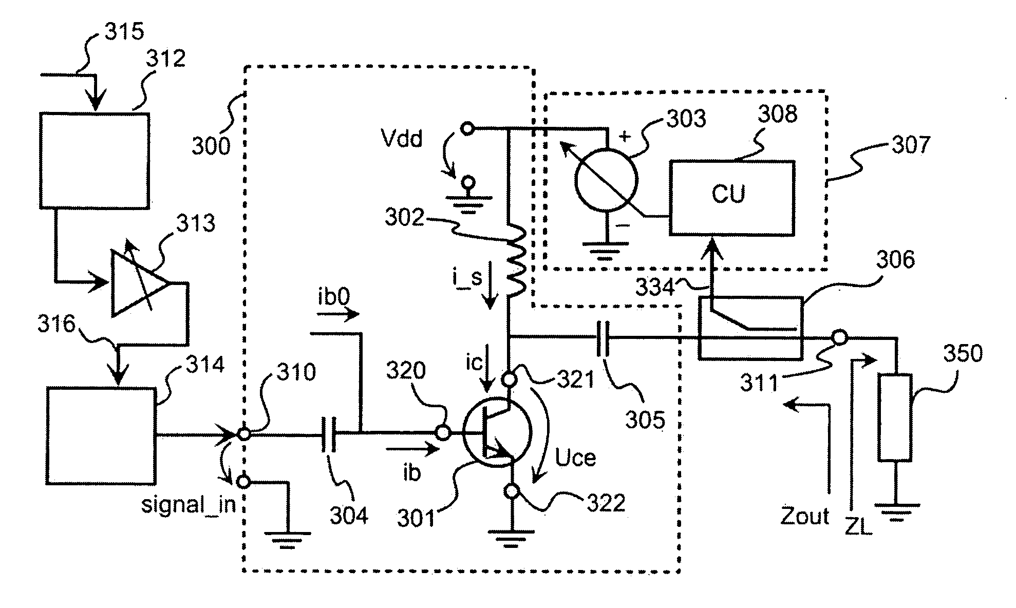
[0045]FIG. 3a shows a transmitter according to an embodiment of the invention. In this embodiment the power amplifier 300 of the transmitter has a single-ended output stage having one bipolar output stage transistor 301. A block 350 represents parts of the transmitter that are loading the power amplifier 300. The block 350 can comprise e.g. a duplexer, an antenna front end, and an antenna. The block 350 is coupled to a signal output interface 311 of the power amplifier 300. The power amplifier receives an input signal at a signal input interface 310. The signal input interface 310 is coupled to a base 320 of the output stage transistor 301 via a dc-decoupling capacitor 304. The base is also fed with dc-current ib0 that partly determines an operating point of the output stage transistor 301. The operating point of the output stage transistor is also determined by supply dc-voltage Vdd that is coupled to a ...


PUM


Abstract

The invention relates to power amplifiers having an adjustable output impedance. A power amplifier according to the invention can be used, for example, for feeding a radio frequency transmission signal into an antenna of a mobile communication device. The real part of an output impedance of a power amplifier according to the invention is matched with the real part of an impedance loading the power amplifier by adjusting an operating point of an output stage transistor 301 of the power amplifier.

Description

FIELD OF THE INVENTION [0001] The invention relates to a transmitter for communicating devices. The invention especially relates to a transmitter having a power amplifier an output impedance of which is adjustable. BACKGROUND OF THE INVENTION [0002] In an electrical system maximum power transfer between a load and a source is achieved when impedances of the load and the source are matched with respect to each other, which minimizes reflection losses between the load and the source. In many electrical devices the source is a power amplifier and the load can be e.g. an antenna or a line transformer. For example, in a mobile communication device an antenna impedance varies considerably with frequency and with external circumstances causing impedance mismatch between the antenna and a power amplifier feeding the antenna. An example of an external circumstance that has an effect on the antenna impedance is positions of user's fingers in the vicinity of an antenna, i.e. an ‘finger effect’...

Claims


Application Information

Patent Timeline
Patent Type & Authority Applications(United States)
IPC IPC(8): H03G3/10
CPCH03F1/0205H03F3/195H03F2200/391H03F3/26H03F2200/387H03F3/24
Inventor AUTTI, MARKO
Owner NOKIA TECHNOLOGLES OY
Learn More