
Barrier device of a three-dimensional liquid crystal display

a liquid crystal display and barrier device technology, applied in optics, instruments, electrical appliances, etc., can solve the problems of unsatisfactory display quality, complex structure of 3d display devices, and insatiable conscious requirements, so as to improve the drawback of resolution and backlight transmissivity, reduce the number of parallax barriers, and enhance image resolution and light transmissivity

Inactive Publication Date: 2007-03-15
WINTEK CORP
View PDF2 Cites 49 Cited by
  • Summary
  • Abstract
  • Description
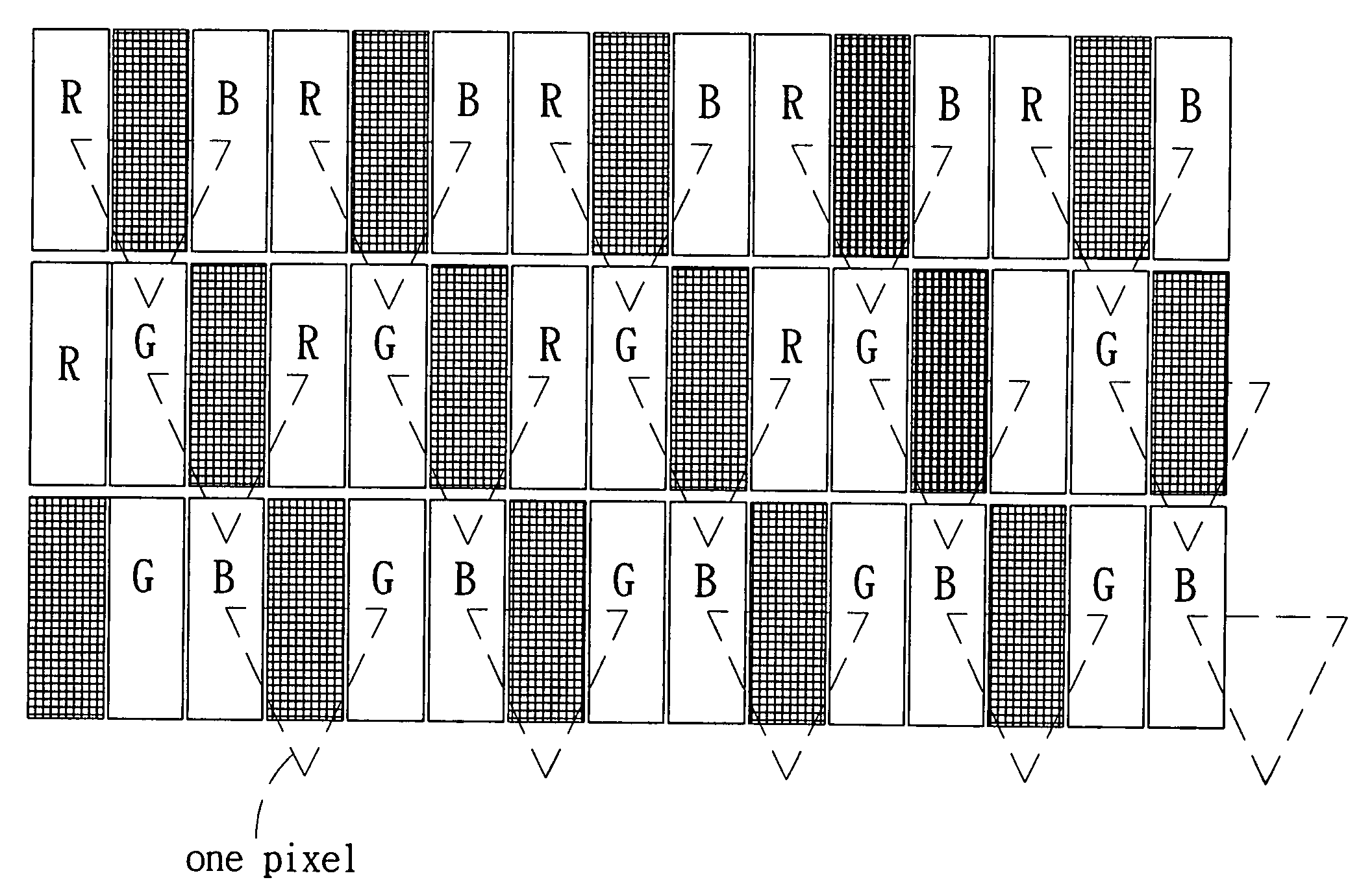
  • Claims
  • Application Information

AI Technical Summary

Benefits of technology

[0008] Consequently, the main purposes of the present invention are reducing the number of the parallax barrier, enhancing the image resolution and light transmissivity of a traditional 3D LCD, and improving the drawbacks that the resolution and backlight transmissivity drop while 2D images are transformed to 3D images of a display.
[0009] Another purpose of the present invention is that by way of the special arrangement for the parallax barriers to split a part of lights into two beams when the parallax barriers of the LCD are activating (shelter light), and the two beams enter the left and right eye respectively to form the parallax so as to achieve the 3D effect. At the same time, sub-pixels utilize the delta array or mosaic array sub pixel rendering to make the 3D image resolution of the present invention greater than that of the conventional and even preserve the resolution under 2D mode so as to achieve the effect of unchanged resolution.
[0012] Further, reducing the number of the parallax barriers appropriately can substantially improve the drawback of the insufficient luminance, i.e. improving the transmissivity of the whole display panel and increasing the luminance and resolution of the display panel.

Problems solved by technology

However, it is surprising that the subconscious requirement is not satisfied due to the obstacle of technology for a long time, and human eyes accept 2D pictures without any resistance.
Usually, a 3D display device has a complicated structure and the displayed quality is not satisfactory.
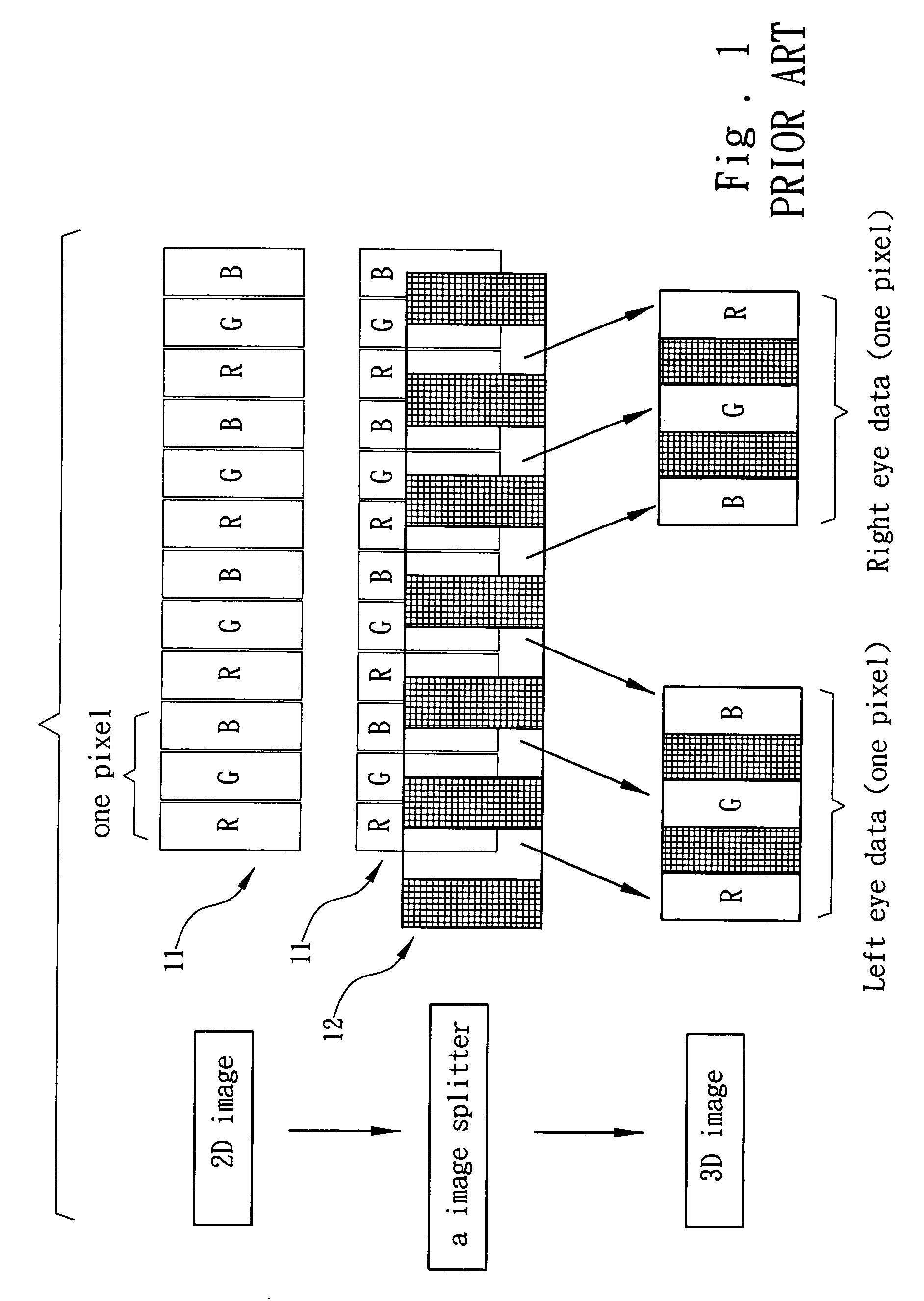
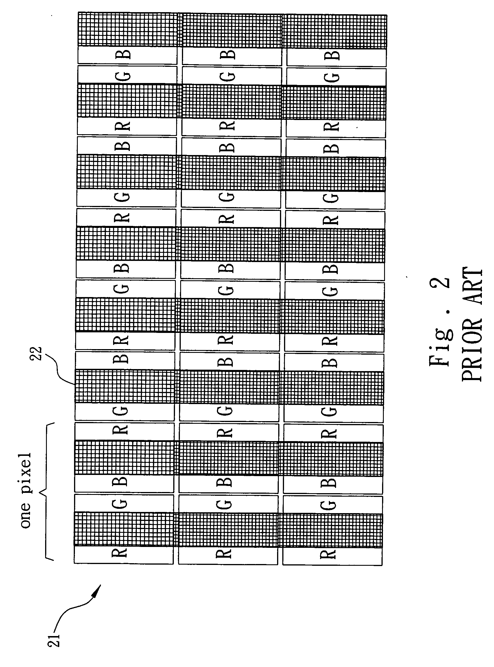
But this method is same as the well-known method, the present problem is that separating a plane image into left and right will result in decreasing resolution and backlight transmissivity at least 50% for 3D display compared with those for 2D display, which affects the display effect.

Method used


Image

  • Barrier device of a three-dimensional liquid crystal display
  • Barrier device of a three-dimensional liquid crystal display
  • Barrier device of a three-dimensional liquid crystal display

Examples


Embodiment Construction

[0026] The detailed descriptions for content and technology of this invention associate with figures are as follows.

[0027] Please refer to FIGS. 4 and 5 together. A color filter 31 on the LCD device of this invention has plural pixels, and each pixel ranks plural sub-pixels (as shown in FIG. 4, a pixel includes red, green, and blue three sub-pixels). A barrier panel 40 (as shown in FIG. 5) is located at the up of the LCD device that includes the color filter 31, or is located at the down of the LCD device that includes the color filter 31.

[0028] The barrier panel 40 equips plural parallax barriers 41 that are grille array and not transparent. The parallax barriers 41 are relative to the pixel of the color filter, and there is a transparent area 42 between two parallax barriers 41 respectively. Moreover, the parallax barriers 41 in the adjacent arrays of the barrier panel 40 are formed diagonally in the same direction, and the width of the transparent area 42 is greater than that o...


PUM


Abstract

A barrier device of a three-dimensional liquid crystal display (3D LCD) device, which aims to the pixels on the color filter, the barrier panel equips plural parallax barriers. Each of the barriers is grille array, and not transparent. There is a transparent area between two parallax barriers. The parallax barriers in the adjacent arrays are formed diagonally, and the width of the transparent area is greater than that of a sub-pixel in order to reduce the number of the parallax barriers, to enhance the luminance of the 3D LCD, and to preserve the resolution of the 2D-display images.

Description

FIELD OF THE INVENTION [0001] The present invention relates to a method that aims to the resolution and the luminance of a 3D LCD (three-dimensional liquid crystal display), mainly aims to the arrangement of the parallax barriers by reducing the number of the parallax barriers to enhance the luminance of the images, and by way of the mixed-color arrangement for sub-pixels to preserve the resolution of the 2D-display images. BACKGROUND OF THE INVENTION [0002] Human eyes are used to 3D images in daily life so the frames including movies and other displays are supposed to be 3D pictures. However, it is surprising that the subconscious requirement is not satisfied due to the obstacle of technology for a long time, and human eyes accept 2D pictures without any resistance. [0003] Usually, a 3D display device has a complicated structure and the displayed quality is not satisfactory. In other words, most 3D displays need special glasses or change the way of input, hence the operators need t...

Claims


Application Information

Patent Timeline
IPC IPC(8): G02F1/1335G02B30/32
CPCG02B5/201G02B27/2214G02F1/133512H04N13/0422H04N13/0409H04N13/0415G02F2201/52H04N13/324H04N13/31H04N13/317G02B30/32G02B30/27
Inventor WU, YI-CHUNLIAO, WEN-JUIWU, FA-CHEN
Owner WINTEK CORP
Learn More