Take-up spool for a printer

a technology for printers and spools, which is applied in printing, inking apparatus, other printing apparatus, etc., can solve the problems of cumbersome securing of print media to the take-up spool, deterioration of print quality, and inability to remove print media conveniently, so as to avoid “dead space”

Inactive Publication Date: 2007-03-15
ZAMTEC +1
View PDF11 Cites 8 Cited by
  • Summary
  • Abstract
  • Description
  • Claims
  • Application Information

AI Technical Summary

Benefits of technology

[0041] Optionally, the shaft has a longitudinal slit. The longitudinal slit optionally extends along the entire length of the shaft and has several functions. Firstly, it allows facile radial expansion of the shaft when, for example, expander plugs are inserted in each end. Secondly, the slit allows a web of material to be securely captured by the spool without the need for adhesive tape or the like. By simply inserting a leading edge of the web inside the slit and rotating the spool, the web can be initially secured to the spool by the frictional gripping action of a longitudinal edge of the slit with a surface of the web in contact therewith. Thereafter, successive overlaying of the web against itself ensures security with the shaft.
[0042] An additional advantage of the longitudinal slit is that the web of material is, at least to some extent, naturally self-aligning once inserted in the slit. By “self-aligning”, it is meant that the material will evenly overlay against itself when the spool rotates, rather than skewing in one direction as the roll of wound material builds up on the spool. Self-alignment may be assisted by appropriate flanges. The flanges may be at each end of the shaft and, as mentioned above, the expander plugs may comprise suitable flanges. In cases where the web of material has a relatively small width dimension, the shaft may be equipped with circumferential flange(s) slidingly movable along the length of the shaft. Such slidably movable circumferential flange(s) may be positioned to guide the web of material onto the spool during initial loading and / or during subsequent printing.
[0043] Optionally, the expander plug(s) are hollow, each having a slit corresponding with and alignable with the longitudinal slit in the shaft. An advantage of this slit in the plug(s) is that the web of material can be secured to the shaft along its entire length, thereby allowing the material to lie flush against flanges at each end of the shaft. Hence, the plug slits advantageously avoid “dead space” at each end of the spool.

Problems solved by technology

Any variation in web speed or web tension would result in a deterioration in print quality in the form of, for example, a distorted printed image.
Current methods for securing the print media to the take-up spool are cumbersome and, moreover, do not allow convenient removal of the print media from the take-up spool once printing has finished.
A problem with this method of loading and unloading the take-up spool is that the user needs to use adhesive tape or similar, which is awkward and not always conveniently available.
A further problem is that a supply of empty take-up spools is required in order to run successive print jobs.

Method used


Image

  • Take-up spool for a printer
  • Take-up spool for a printer
  • Take-up spool for a printer

Examples


Embodiment Construction

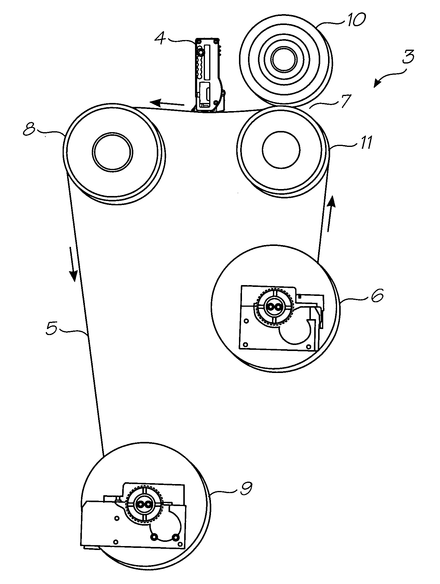
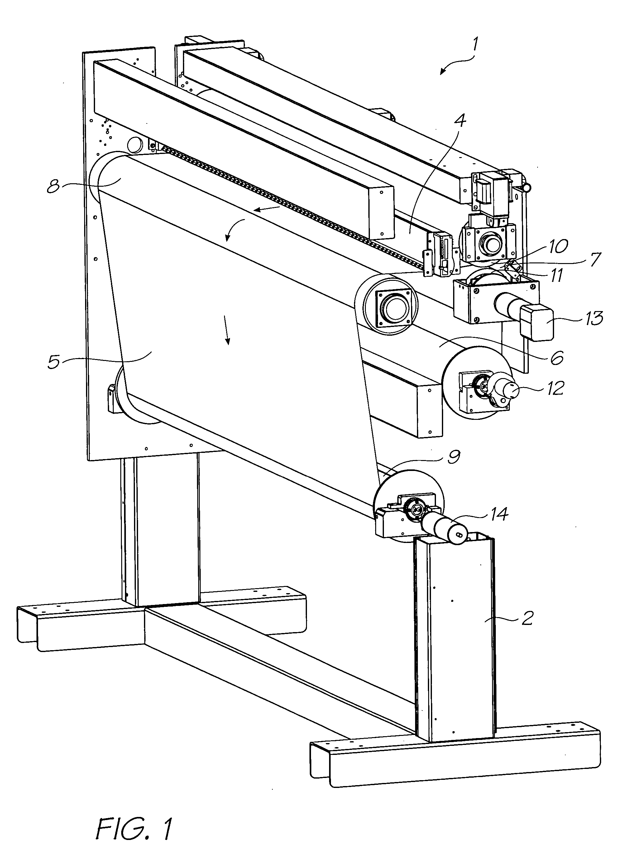
[0053] Referring to FIGS. 1 and 2 there is shown a wide format printer 1 comprising a support structure 2, which supports a feed mechanism 3 and a printhead 4. The feed mechanism 3 comprises a system of motorized rollers for feeding a web of print media 5 past the printhead 4. The printhead 4 is a pagewidth inkjet printhead, which ejects droplets of ink onto the web 5 as it is fed through a print zone adjacent the printhead 4. The direction of feed is shown by arrows on the web 5.

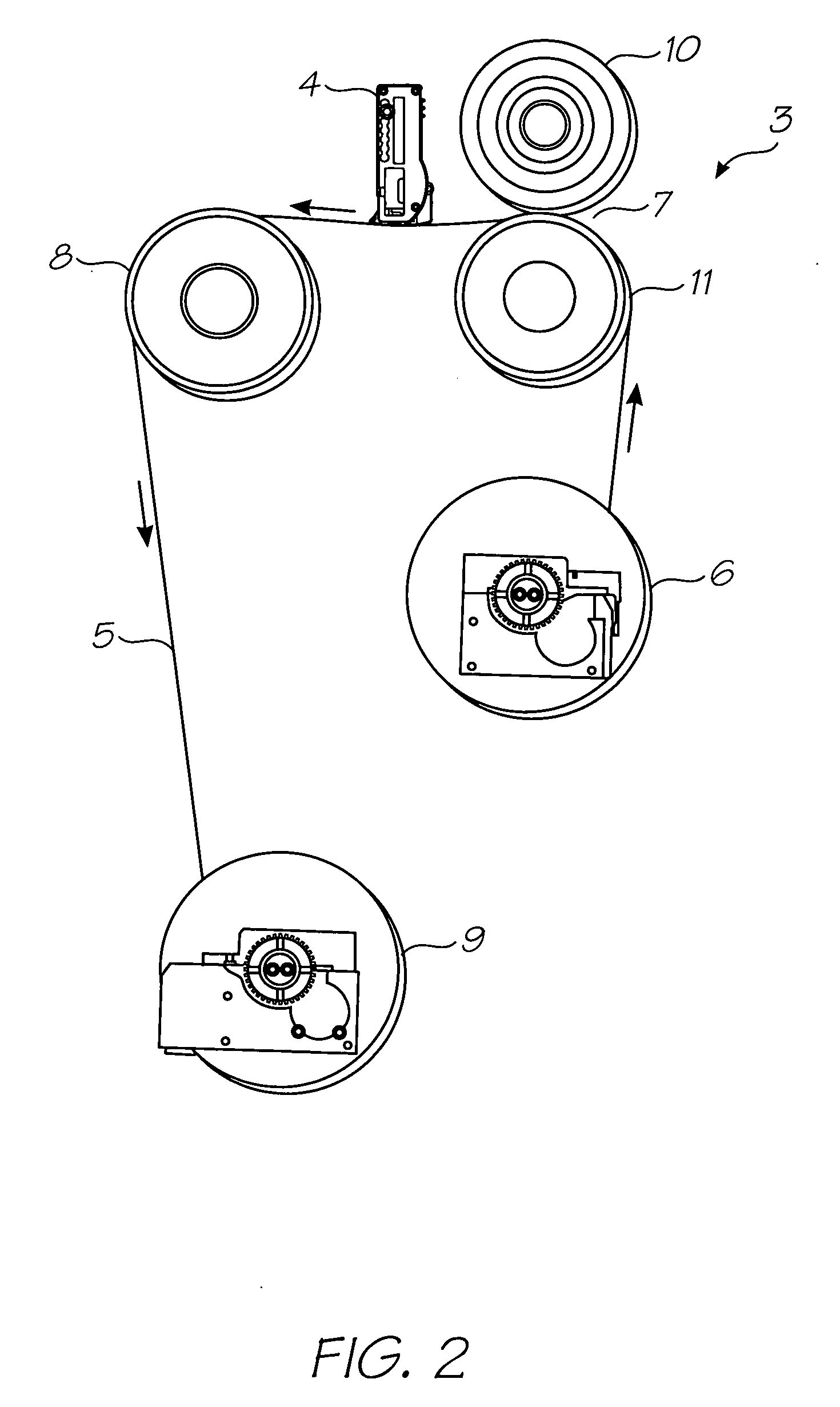
[0054]FIG. 2 shows in more detail the feed mechanism 3 comprising a supply spool 6, a drive roller system 7, an idle roller 8 and a take-up spool 9. The supply spool 6 is loaded with a web 5 of print media, which is fed to the drive roller system 7. The drive roller system 7 comprises an upper drive roller 10 in gripping engagement with a lower drive roller 11, the web 5 being fed between the upper drive roller 10 and the lower drive roller 11. From the drive roller system 7, the web is fed past the printh...


PUM


Abstract

A take-up spool for a wide format printer is provided. The spool comprises a radially expandable shaft and at least one expander releasably engageable with the shaft. Engagement of the expander with the shaft radially expands at least part of the shaft. Expansion and contraction of the shaft facilitates removal of a web of print media wound onto the shaft.

Description

CROSS REFERENCES TO RELATED APPLICATIONS [0001] Various methods, systems and apparatus relating to the present invention are disclosed in the following co-pending applications filed by the applicant or assignee of the present invention. The disclosures of all of these co-pending applications and granted patents are incorporated herein by cross-reference. 09 / 517539656685809 / 11276263319466246970644252509 / 51738409 / 505951637435409 / 517608681696867578326334190674533109 / 51754110 / 20355910 / 20356010 / 20356410 / 63626310 / 63628310 / 86660810 / 90288910 / 90283310 / 94065310 / 94285810 / 72718110 / 72716210 / 72716310 / 72724510 / 72720410 / 72723310 / 72728010 / 72715710 / 72717810 / 72721010 / 72725710 / 72723810 / 72725110 / 72715910 / 72718010 / 72717910 / 72719210 / 72727410 / 72716410 / 72716110 / 72719810 / 72715810 / 75453610 / 75493810 / 72722710 / 72716010 / 93472010 / 296522679521510 / 29653509 / 5751096805419685928909 / 6079856398332639457366229236747760692114410 / 88488110 / 94394110 / 94929411 / 03986611 / 12301111 / 12301011 / 14476911 / 14823710 / 92284610 / 92284510 / 8545...

Claims


Application Information

Patent Timeline
Patent Type & Authority Applications(United States)
IPC IPC(8): B41J15/04B41J15/16
CPCB41J15/02B65H75/245B65H75/22B41J2202/21B65H75/2245
Inventor SILVERBROOK, KIARAMACHANDRA, NAGESHWASZCZUK, JAN
Owner ZAMTEC
Why Eureka
Try Eureka