
Wireless terminal, base device, wireless system, wireless terminal control method, wireless terminal control program, and computer-readable storage medium storing same program

a technology of wireless terminals and control methods, applied in the direction of selective content distribution, two-way working systems, television systems, etc., can solve the problem that users have no way of knowing whether an image has been interrupted

Inactive Publication Date: 2007-03-15
SHARP KK
View PDF15 Cites 67 Cited by
  • Summary
  • Abstract
  • Description
  • Claims
  • Application Information

AI Technical Summary

Benefits of technology

[0018] Therefore, the foregoing wireless terminal makes it possible to prevent the user from being bothered by a feeling of discomfort even when an image display is interrupted due to transmission channel switching or the like, so that user-friendliness can be improved.
[0020] The foregoing arrangement makes it possible to prevent frequent transmission channel switching and to maintain an optimum communication condition entirely in the network.

Problems solved by technology

However, the transmission channel switching in such a conventional wireless communication device causes interruption of the communication, so that an image is not displayed.
Therefore, the conventional wireless communication device has such a problem that a user has no way of knowing whether an image has been interrupted or a communication terminal has switched transmission channels.

Method used


Image

  • Wireless terminal, base device, wireless system, wireless terminal control method, wireless terminal control program, and computer-readable storage medium storing same program
  • Wireless terminal, base device, wireless system, wireless terminal control method, wireless terminal control program, and computer-readable storage medium storing same program
  • Wireless terminal, base device, wireless system, wireless terminal control method, wireless terminal control program, and computer-readable storage medium storing same program

Examples


Embodiment Construction

[0040] A preferred embodiment of the present invention will be described in detail below with reference to the accompanying drawings.

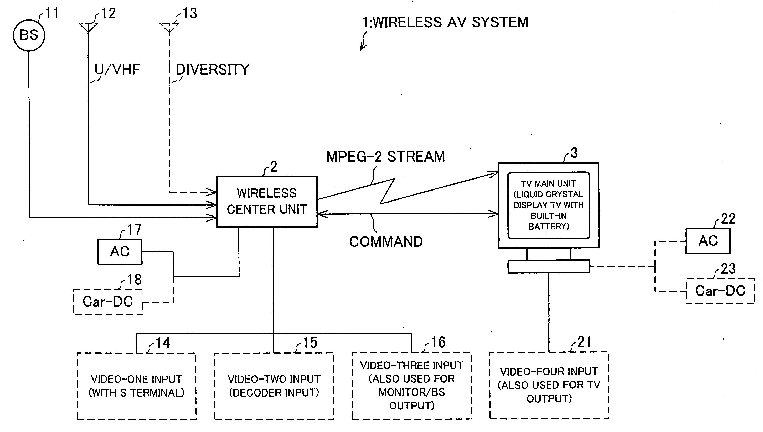
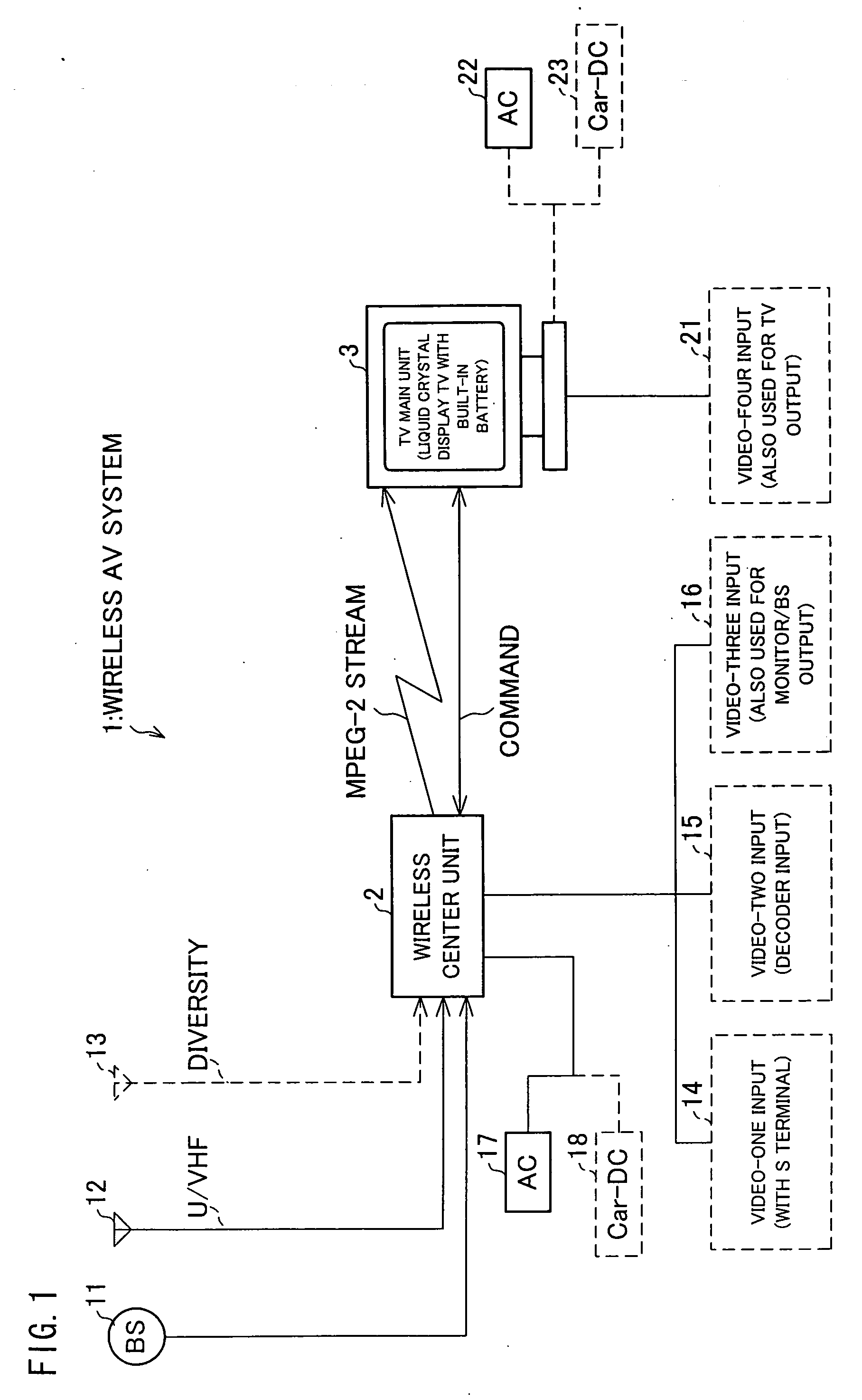
[0041]FIG. 1 is a block diagram showing an arrangement of a wireless AV system 1 according to one embodiment of the present invention. The wireless AV system 1 of the present embodiment is an example of applying the present invention to a separate-display wireless TV receiver. FIG. 10 is an explanatory diagram schematically showing the wireless AV system 1 serving as the separate-display wireless TV receiver.

[0042] As shown in FIGS. 1 and 10, the wireless AV system 1 includes: a central wireless unit 2 serving as a base device; and a television (TV) main unit 3 serving as a portable terminal (wireless terminal). The central wireless unit 2 (wireless communication apparatus, central apparatus) and the TV main unit 3 (wireless communication apparatus, display apparatus) are paired to form a wireless transmission network.

[0043] As shown in FIG. 10, the...


PUM


Abstract

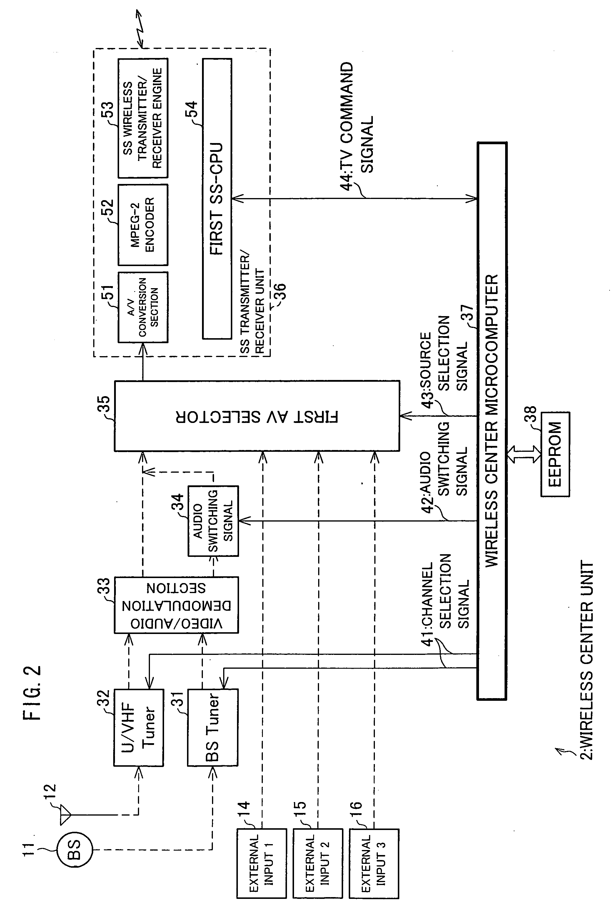
A wireless AV system includes a central wireless unit, serving as a base device, and a TV main unit. The TV main unit includes an SS transmitter / receiver (T / R) unit, a TV section, a TV microcomputer, and a second SS-CPU. The SS T / R unit receives an MPEG-2 stream and command transmission data both of which are transmitted from an SS T / R unit of the central wireless unit, and decodes the MPEG-2 stream and the command transmission data so received. The TV section displays a video signal and outputs an audio signal. The TV microcomputer controls the TV main unit entirely. The second SS-CPU detects a communication condition between the central wireless unit and the TV main unit according to a received radio wave field intensity and a retransmission request made based on an error rate. The TV microcomputer causes the TV section to OSD-display such reception sensitivity information messages that video and / or audio data has been interrupted, that transmission channels are being switched, that connection are being made, and that the TV main unit is out of communication range, according to the. communication condition so detected. Thus, a user is free from a feeling of discomfort even when a display image is interrupted due to transmission channel switching etc. Thus, user-friendliness can be improved.

Description

TECHNICAL FIELD [0001] The present invention relates to a wireless terminal, a base device, a wireless system, a wireless terminal control method, a wireless terminal control program, and a computer-readable storage medium storing the same program. BACKGROUND ART [0002] Along with the recent explosive growth of the Internet, LANs (Local Area Networks) have been set up in more offices and -households. Due in part to improvements in digital wireless communications technologies, there has been a rapidly growing need for a wireless LAN (i.e., a LAN that is set up wirelessly in order to remove the burden of cabling). Furthermore, partly because the wireless LAN can be used in a mobile environment of a mobile terminal as typified by a laptop computer, the wireless LAN is expected to be used in appreciable numbers in the future. A representative technology of the wireless LAN is the IEEE 802.11, which is standardized by the IEEE (Institute of Electrical and Electronics Engineers). This sta...

Claims


Application Information

Patent Timeline
Patent Type & Authority Applications(United States)
IPC IPC(8): H04Q7/20H04N5/00H04N5/38H04N5/44H04N5/445
CPCH04N5/38H04N5/4401H04N5/44513H04N21/485H04N21/41407H04N21/44227H04N21/4122H04N21/426H04N21/47H04B1/40H04N5/44
Inventor SAKAMOTO, KENJI
Owner SHARP KK
Learn More