Recording apparatus

a recording device and recording technology, applied in the field of recording devices, can solve the problems of increasing the size of the product, affecting and unpleasant noise to the ear, so as to prevent the product from falling off and improve the efficiency of assembly work

Active Publication Date: 2018-10-04
SEIKO EPSON CORP
View PDF1 Cites 0 Cited by
  • Summary
  • Abstract
  • Description
  • Claims
  • Application Information

AI Technical Summary

Benefits of technology

[0006]An advantage of some aspects of the invention is that an increase in the size of the apparatus, and the space needed when the apparatus is used can be both suppressed with a configuration including an opening / closing body and a damper that apply damping force when the opening / closing body is closed.
[0011]With the above, the distance between the rotational center of the opening / closing body and the rotation free edge becomes smaller, and the height of the rotation free edge of the opening / closing body can be reduced when the opening / closing body is opened. Accordingly, even when the apparatus is installed in an installation space that is low in height, the opening / closing body can be opened without pulling out the apparatus from the installed space, or even when the opening / closing body cannot be opened completely, a sufficient opening amount can be obtained, and user-friendliness can be improved.
[0013]According to the above, since the attaching member is fixed to the two side frames provided at the two sides of the center frame, the rigidity of the frame body constituted by the center frame and the two side frames can be increased.
[0019]According to the above, in the configuration in which the attaching member is fixed to the center frame, suppression in the size in the apparatus depth direction can be achieved.
[0021]According to the above, since the arm portion, which connects the main body portion of the opening / closing body and the rotational center, has the shape that avoids the edge portion of the top surface member when the opening / closing body is opened / closed, the main body portion and the edge portion of the top surface member can be made to be closer to each other. As a result, in a state in which the opening / closing body is closed, the gap between the main body portion and the edge portion of the top surface member can be made smaller, the entering of dust and the like into the apparatus through the gap can be suppressed, and the appearance of the apparatus can be improved.
[0029]According to the above, since a holding member that is attached to the attaching member and that, in a state in which the holding member is attached to the attaching member, holds the damper is included, the damper can be prevented from falling off when an assembly, which is formed by attaching the damper to the attaching member, is mounted on the apparatus main body; accordingly, the efficiency of the assembly work is improved.

Problems solved by technology

In a case in which the opening / closing body is, particularly, a heavy object such as a scanner described in JP-A-2013-56504 described above, when closing the opening / closing body, the arm-like member needs to be disengaged such that the operation thereof is laborious, and when closing the opening / closing body, if the opening / closing body is closed using its own weight, there is a concern that the impact may be large generating a collision noise that is unpleasant to the ear and that the opening / closing body may be broken.
However, providing a damper increases the size of the product.

Method used


Image

  • Recording apparatus
  • Recording apparatus
  • Recording apparatus

Examples


first exemplary embodiment

Outline of Printer

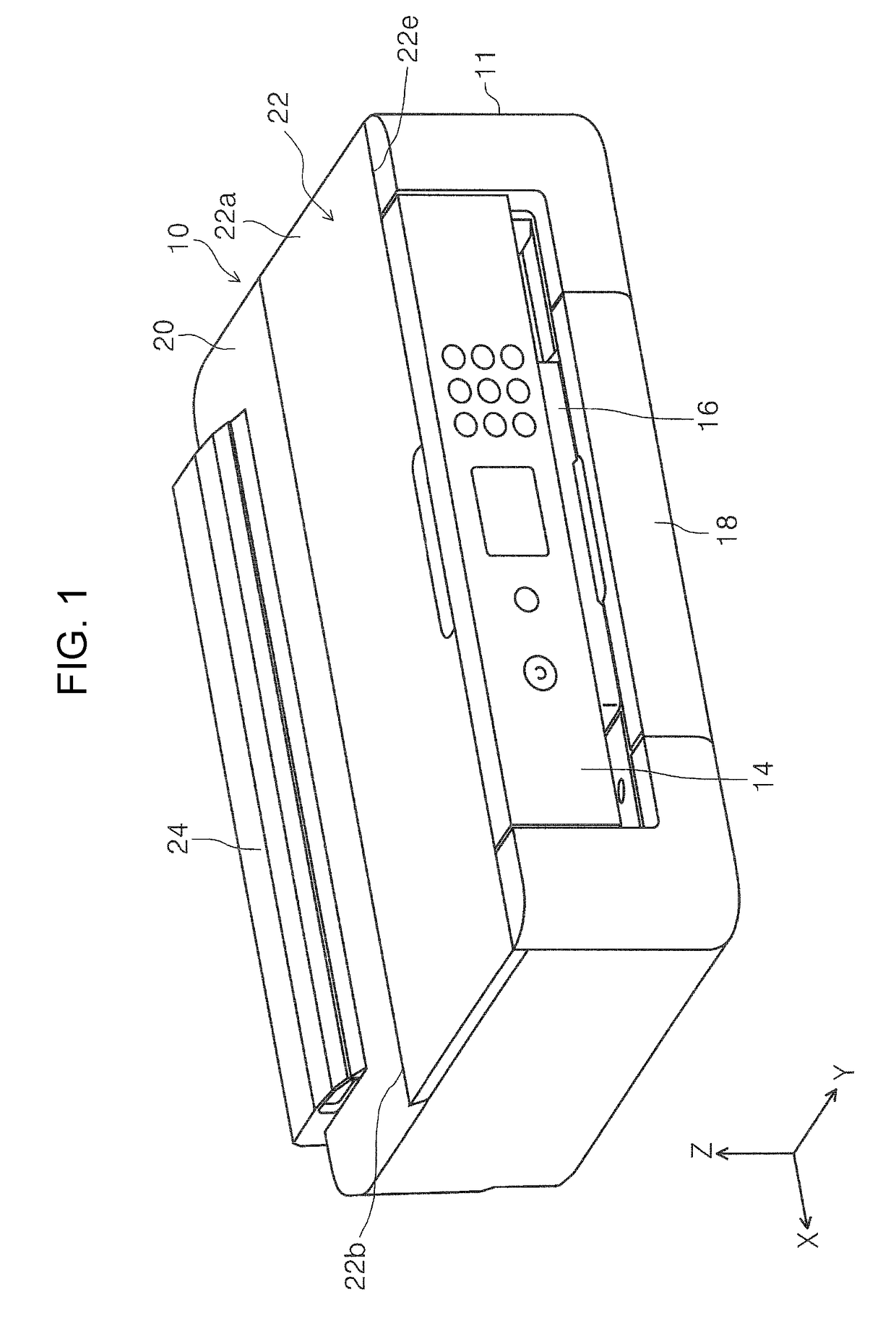
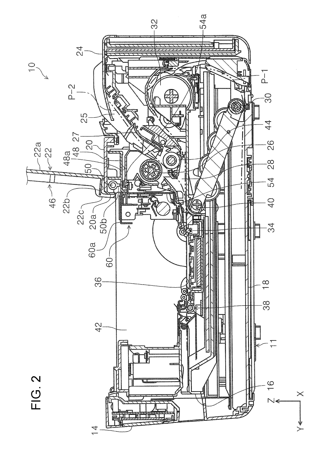
[0055]Referring to FIG. 1, an overall configuration of a printer 10 will be described. The printer 10 is configured as an ink jet printer serving as an example of the recording apparatus. The printer 10 includes a housing and an apparatus main body 11 that constitutes an inside of the housing. An operation unit 14 is provided on an apparatus front side of the apparatus main body 11. Operation members, such as the display panel and switches, are provided in the operation unit 14. A discharge tray 16 is provided in the −Z direction of the operation unit 14. The discharge tray 16 is switchable between a state (FIGS. 1 and 2) in which the discharge tray 16 is accommodated inside the apparatus main body 11 and a state (not shown) in which the discharge tray 16 is developed on the front side of the apparatus main body 11 so as to be projected on the apparatus front side.

[0056]In the apparatus main body 11, a medium accommodating cassette 18 that accommodates a medium the...

second exemplary embodiment

Modifications of First Exemplary Embodiment and Second Exemplary Embodiment

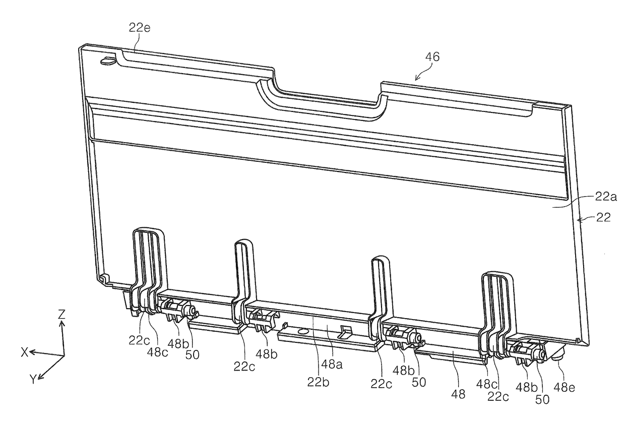
[0094](1) Each exemplary embodiment is configured so that the attaching member 48 is connected to the side frames 56A and 56B. However, instead of the above configuration, the attaching member 48 may be attached to the center frame 54.

[0095](2) In each exemplary embodiment, the cables 66 and 68 are wired along the sheet metal member 64 or the holding member 70. However, instead of the above configuration, a cut-out portion may be provided in the base body portion 48a of the attaching member 48 so that communication is established in the X-axis direction in FIG. 13, and the cables 66 and 68 may be wired so as to extend in the X-axis direction through the cut-out portion. The above configuration allows the space inside the base body portion 48a to be used effectively, and a space for laying the cables 66 and 68 to be provided separately; accordingly, the space of the apparatus can be saved.

[0096]The above descr...


PUM


Abstract

A recording apparatus including a housing, an apparatus main body that constitutes an inside of the housing, the apparatus main body including a recording member that performs recording, a feed roller that feeds a medium, the medium being set at an inclined position, towards the recording member, an opening / closing body that opens / closes a portion above an area in which the recording member is disposed, and a damper that applies damping force to the opening / closing body when the opening / closing body is closed. The opening / closing body and the damper are attached to the apparatus main body through an attaching member disposed at an area above the feed roller.

Description

BACKGROUND1. Technical Field[0001]The present invention relates to a recording apparatus that performs recording on a medium.2. Related Art[0002]In recording apparatuses, representative examples of which are fax machines and printers, there are cases in which an opening / closing body is provided above a moving area of a carriage including a recording head. There are cases in which the opening / closing body is merely a cover, or is a scanner as described in JP-A-2013-56504 and JP-A-2006-23575.[0003]In JP-A-2013-56504, a configuration is disclosed in which a state in which a scanner unit 12 is open is maintained by an arm-like member (a sliding member 77). Furthermore, JP-A-2006-23575 discloses a configuration in which a hinge is configured by a damper.[0004]In a case in which the opening / closing body is, particularly, a heavy object such as a scanner described in JP-A-2013-56504 described above, when closing the opening / closing body, the arm-like member needs to be disengaged such that...

Claims


Application Information

Patent Timeline
Patent Type & Authority Applications(United States)
IPC IPC(8): B41J29/10B41J29/13
CPCB41J29/10B41J29/13B41J13/02B41J13/10B41J29/02B41J29/12
Inventor TOGO, KATSUMIAKAHANE, HISAYUKISHIROTA, KENICHI
Owner SEIKO EPSON CORP
Why Eureka
Try Eureka