Ultrasonic sensor mounting structure
a technology for ultrasonic sensors and mounting structures, which is applied in the direction of vehicular safety arrangements, using reradiation, instruments, etc., can solve the problems of reducing affecting the accuracy of mounting, and affecting the reliability of ultrasonic sensors, so as to prevent the reduction of sensor characteristics and accurate mounting
- Summary
- Abstract
- Description
- Claims
- Application Information
AI Technical Summary
Benefits of technology
Problems solved by technology
Method used
Image

Examples
first embodiment
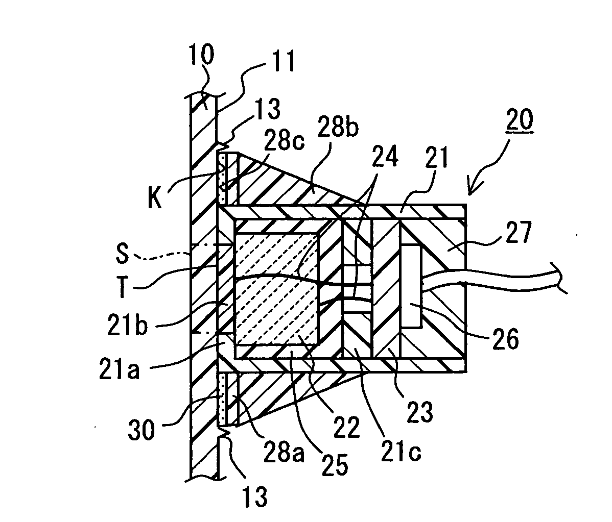
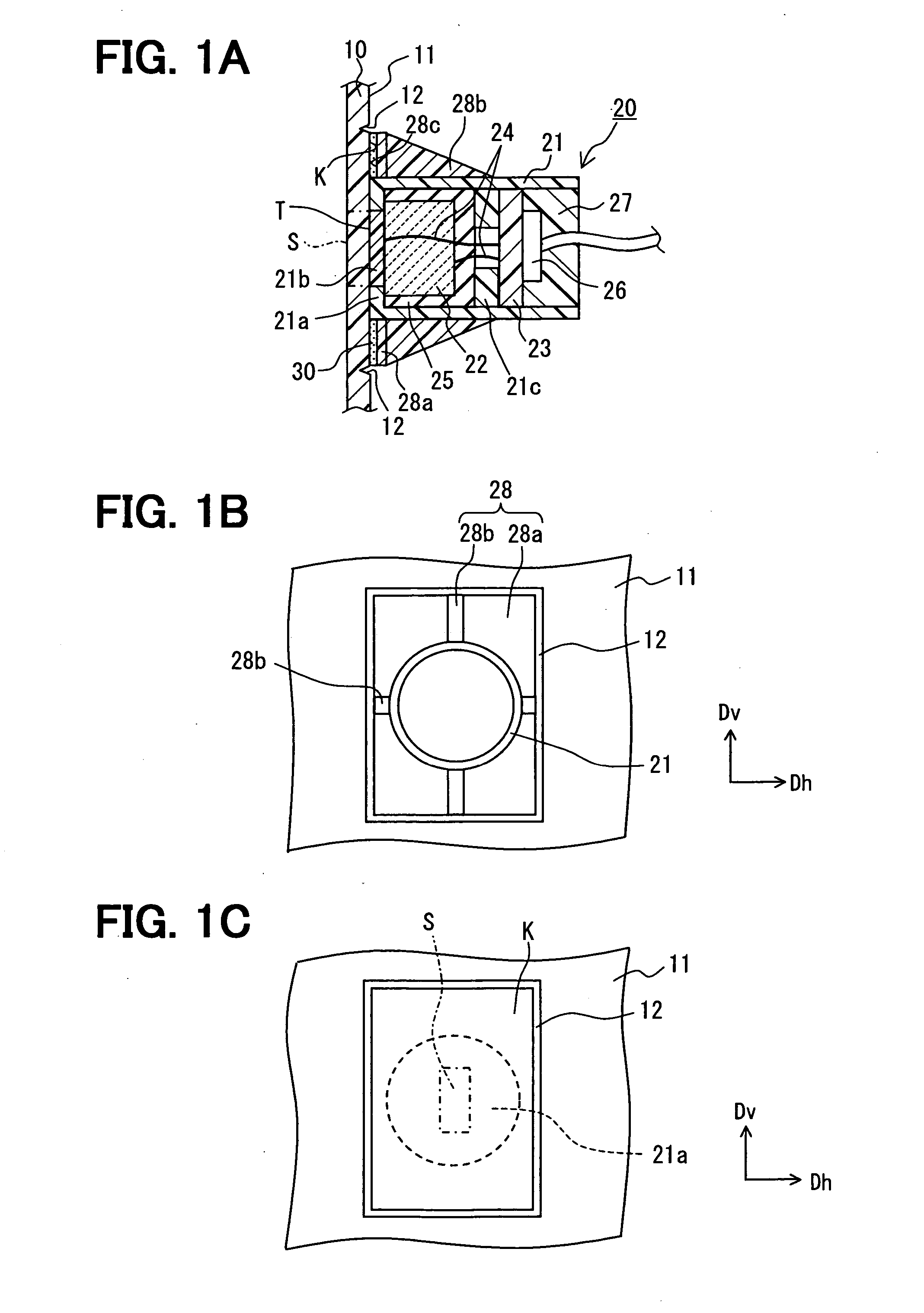
[0023] As shown in FIGS. 1A-1C, the ultrasonic sensor 20 includes a cylindrical body 21 with a bottom wall 21a, an ultrasonic transducer 22, and a circuit board 23 having a processing circuit that calculates a distance from the ultrasonic sensor 20 to an object based on an ultrasonic vibration (wave) emitted and received by the ultrasonic transducer 22. The ultrasonic sensor 20 is mounted to an inner surface 11 of a wall member 10 and uses a portion of an outer surface of the wall member 10 as a vibrating surface S. The wall member 10 may be, for example, a vehicle bumper made of synthetic resin.
[0024] The ultrasonic transducer 22 is made of piezoceramic and attached to the bottom wall 21a of the body 21. The piezoceramic is made by compressing and firing metal oxide powder such as barium titanate powder. Since the ultrasonic transducer 22 not only emits the ultrasonic vibration but also receives the ultrasonic vibration, the ultrasonic sensor 20 does not need two ultrasonic transd...
second embodiment
[0054] In the second embodiment shown in FIGS. 8A and 8B, a wall member 10 includes an uneven portion 14 instead of or in addition to the recessed line 12. The uneven portion 14 is partially or wholly provided on the fixation portion K. Thus, the uneven portion 14 can act as the mounting location mark when the ultrasonic sensor 20 is mounted to the wall member 10.
[0055] The fixing surface 28c of the ultrasonic sensor 20 is bonded to the fixation portion K by an adhesive member 30 that is a liquid adhesive such as an ultraviolet curing adhesive. Since the uneven portion 14 is provided all over the fixation portion K, the adhesive member 30 penetrates into small gaps on the fixation portion K. As a result, the bonding area between the fixing surface 28c and the fixation portion K is increased so that an anchor effect can be obtained. Thus, the ultrasonic sensor 20 can be securely mounted to the wall member 10.
[0056] In the wall member 10, a fixing surface potion containing the fixat...
third embodiment
[0058] In the third embodiment shown in FIGS. 9A-9C, a wall member 10 includes three mounting poles 15 extending perpendicular to the inner surface 11 and a ultrasonic sensor 20 includes three mounting holes 28d corresponding to the mounting poles 15.
[0059] The mounting member 28 has a circular shape with a center opening where the body 21 of the ultrasonic senor is positioned. The mounting holes 15 are penetrating holes that penetrate the mounting member 28 or recessed holes that do not penetrate the mounting member 28. The mounting poles 15 (holes 28d) are arranged such that a line connecting the mounting poles 15 does not form a regular triangle. For example, the line may form an isosceles triangle. In such an approach, the ultrasonic sensor 20 can be mounted to the wall member 10 in the correct orientation by inserting the mounting poles 15 into or through the mounting holes 28d. Thus, the ultrasonic sensor 20 can be directional in the desired direction. While the ultrasonic se...
PUM
 Abstract
Description
Claims
Application Information
 - R&D
- Intellectual Property
- Life Sciences
- Materials
- Tech Scout
- Unparalleled Data Quality
- Higher Quality Content
- 60% Fewer Hallucinations
Browse by: Latest US Patents, China's latest patents, Technical Efficacy Thesaurus, Application Domain, Technology Topic, Popular Technical Reports.
© 2025 PatSnap. All rights reserved.Legal|Privacy policy|Modern Slavery Act Transparency Statement|Sitemap|About US| Contact US: help@patsnap.com