Mobile communication device and an antenna assembly for the device

a mobile communication and antenna technology, applied in the field of mobile communication, can solve the problems of severe breakthrough between the pifa and the gps receiver, no useful signal reception via the dielectrically loaded antenna, etc., and achieve the effect of reducing breakthrough

Inactive Publication Date: 2007-03-22
SARANTEL LTD
View PDF9 Cites 49 Cited by
  • Summary
  • Abstract
  • Description
  • Claims
  • Application Information

AI Technical Summary

Benefits of technology

[0016] By locating the dielectrically-loaded antenna, including its balun, at the end of the elongate radiator structure of the first antenna, the ability of the first antenna to radiate energy at the primary operating frequency of the second antenna is curtailed, as will be described in more detail hereinafter, thereby reducing breakthrough from a transmitter coupled to the first antenna to receiving circuitry coupled to the second antenna.

Problems solved by technology

It has been found that if a dielectrically-loaded antenna such as those described in the above-mentioned patents is incorporated, together with a GPS receiver in a mobile telephone having a PIFA for transmitting and receiving terrestrial signals, severe breakthrough occurs between the PIFA and the GPS receiver when the mobile telephone transmitter is on.
In general, the breakthrough is such that there may be no useful signal reception via the dielectrically-loaded antenna when the mobile telephone transmitter is on.

Method used


Image

  • Mobile communication device and an antenna assembly for the device
  • Mobile communication device and an antenna assembly for the device
  • Mobile communication device and an antenna assembly for the device

Examples


Embodiment Construction

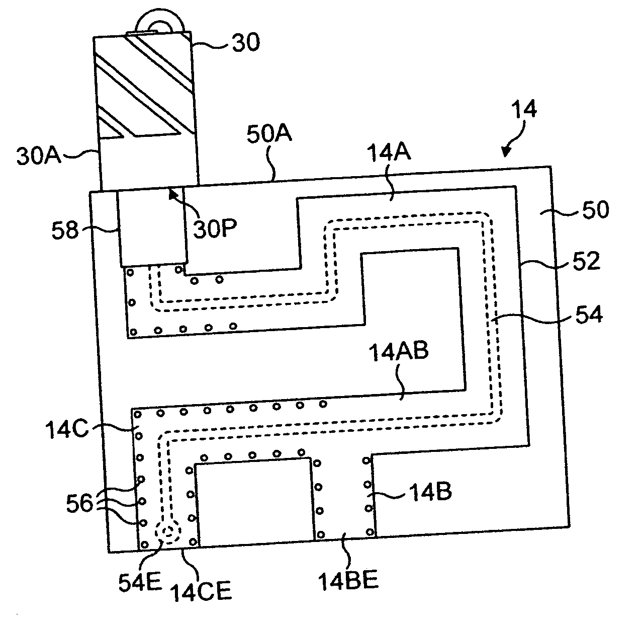
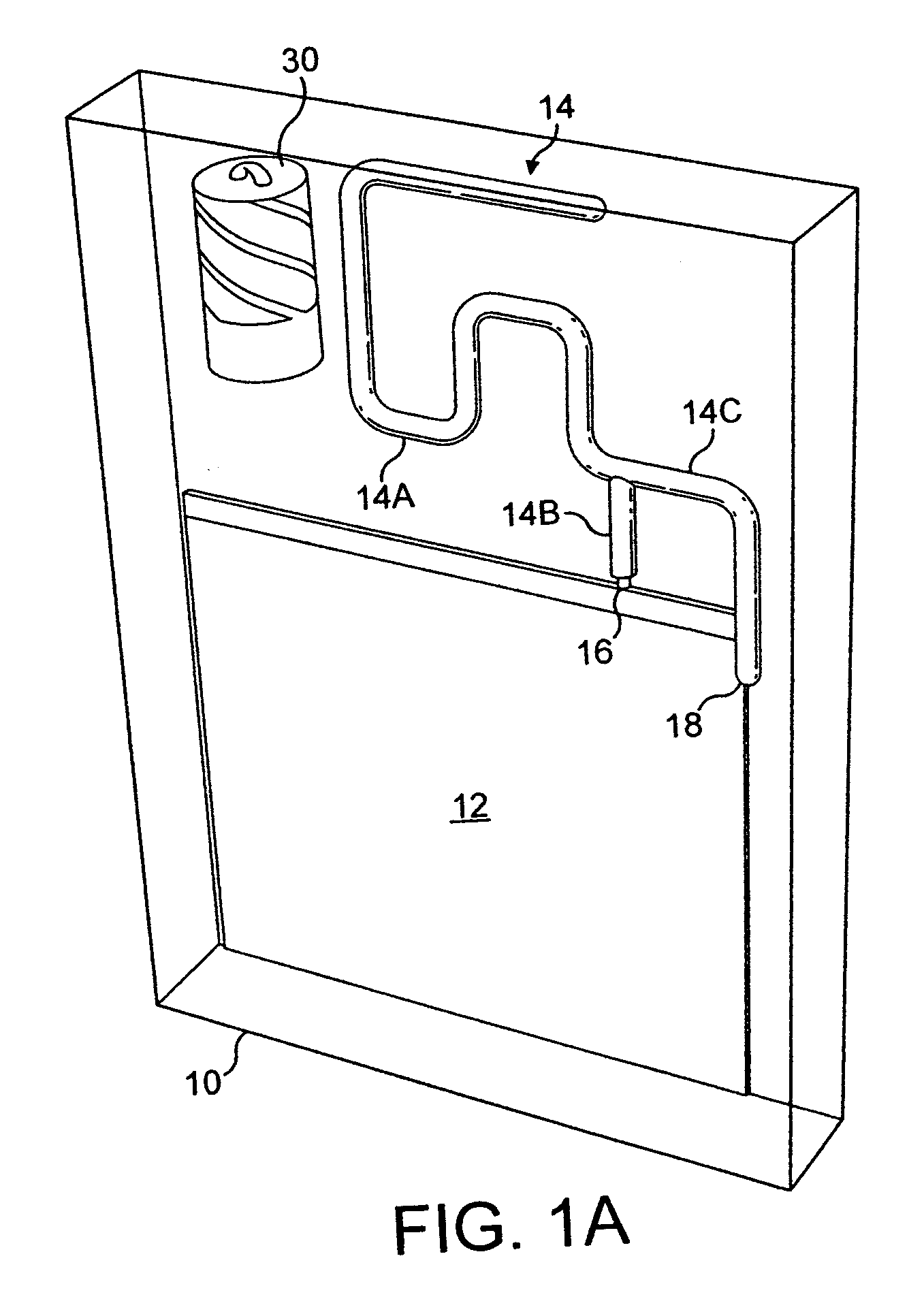
[0025] As stated above, it has been found that if a dielectrically-loaded helical antenna provided, e.g., for receiving GPS signals is incorporated in a mobile telephone having an inverted-F antenna for transmitting and receiving telephone signals, breakthrough occurs between the telephone transmitter, coupled to the inverted-F antenna, and a GPS receiver coupled to the dielectrically-loaded antenna. Such a combination of antennas is diagrammatically illustrated in FIG. 1A as part of a mobile communication device 10 having a main printed circuit board 12. For the purposes of this illustration, the inverted-F antenna 14 is composed of wire elements, specifically a resonant radiating branch element 14A the base of which is connected to a first radio frequency (RF) port 16 on the printed circuit board 12 by a feed connection element 14B. To provide an impedance match, the base of the radiating branch element 14A is also connected to a ground connection 18 on the board 12 by a shunt ele...


PUM


Abstract

A mobile communication device has an antenna assembly comprising the combination of an inverted-F antenna and a dielectrically-loaded quadrifilar helical antenna, the latter mounted on the distal end of an elongate radiator element of the inverted-F antenna. The dielectrically-loaded antenna has an integral balun on a ceramic antenna core, the balun providing a balanced feed for the radiating elements of the antenna The elongate radiator structure of the inverted-F antenna acts as a feed path for the dielectrically-loaded antenna, the feed path extending along the elongate radiator structure from the balun to a ground connection element of the inverted-F antenna and, thence, to a signal port associated with a grounding connection of the inverted-F antenna Placing the dielectrically-loaded quadrifilar antenna at the end of the radiator structure of the inverted-F antenna rather than alongside the latter substantially reduces breakthrough from a transmitter coupled to the inverted-F antenna to receiving circuitry coupled to the dielectrically-loaded antenna.

Description

CROSS-REFERENCE TO RELATED APPLICATION [0001] This application is related to, and claims a benefit of priority under one or more of 35 U.S.C. 119(a)-119(d) from copending foreign patent application 0519371.9, filed in the United Kingdom on Sep. 22, 2005 under the Paris Convention, the entire contents of which are hereby expressly incorporated herein by reference for all purposes. FIELD OF THE INVENTION [0002] This invention relates to a mobile communication device comprising radio frequency (RF) circuitry and an antenna assembly coupled to the circuitry. BACKGROUND OF THE INVENTION [0003] The assignee of the present applicant is the registered proprietor of a number of patents and patent applications which disclose dielectrically-loaded antennas for operation at frequencies in excess of 200 MHz. Examples of such patents are GB2292638B, GB2310543B and GB2367429B. In each case, the antenna comprises an electrically insulative antenna core of a solid material having a relative dielectr...

Claims


Application Information

Patent Timeline
Patent Type & Authority Applications(United States)
IPC IPC(8): H01Q1/24H01Q5/10H01Q9/04H01Q11/08H01Q21/30
CPCH01Q9/0421H01Q21/30H01Q11/08H01Q9/42H01Q5/40H01Q1/243H01Q1/521H01Q5/00H01Q21/28H01Q1/24H01Q9/04
Inventor LEISTEN, OLIVER PAUL
Owner SARANTEL LTD
Why Eureka
Try Eureka