Perpendicular magnetic recording head and method of manufacturing the same

a technology of magnetic recording head and perpendicular magnetic field, which is applied in the direction of magnetic recording head, data recording, instruments, etc., can solve the problems of inability to improve the intensity and the gradient and difficulty in sufficiently increasing the magnetic field gradient, so as to improve the gradient and the intensity of the recording magnetic field

Active Publication Date: 2007-03-22
TDK CORPARATION
View PDF7 Cites 20 Cited by
  • Summary
  • Abstract
  • Description
  • Claims
  • Application Information

AI Technical Summary

Benefits of technology

[0023] According to present embodiments, a gap between a main magnetic pole layer and a return path layer is set to be small at a position close to a surface facing a recording medium, and is set to be large at the rear in a height direction. Therefore, it is possible to obtain a perpendicular magnetic recording head capable of improving a gradient and an intensity of a recording magnetic field, and a method of manufacturing the perpendicular magnetic recording head.

Problems solved by technology

However, since the magnetic flux returning from the main magnetic pole layer toward the return path layer is likely to be dispersed, it is difficult to sufficiently increase the gradient of the magnetic field.
Therefore, it is not possible to improve the intensity and the gradient of the recording magnetic field at the same time.

Method used


Image

  • Perpendicular magnetic recording head and method of manufacturing the same
  • Perpendicular magnetic recording head and method of manufacturing the same
  • Perpendicular magnetic recording head and method of manufacturing the same

Examples


first embodiment

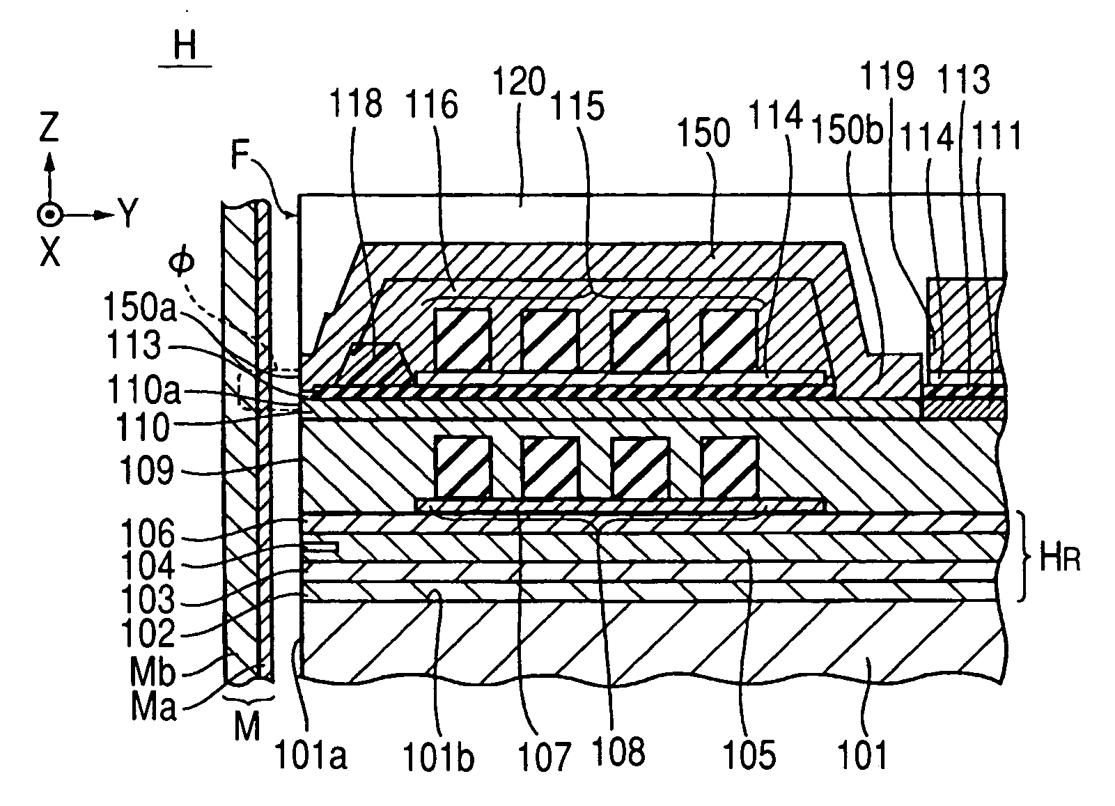
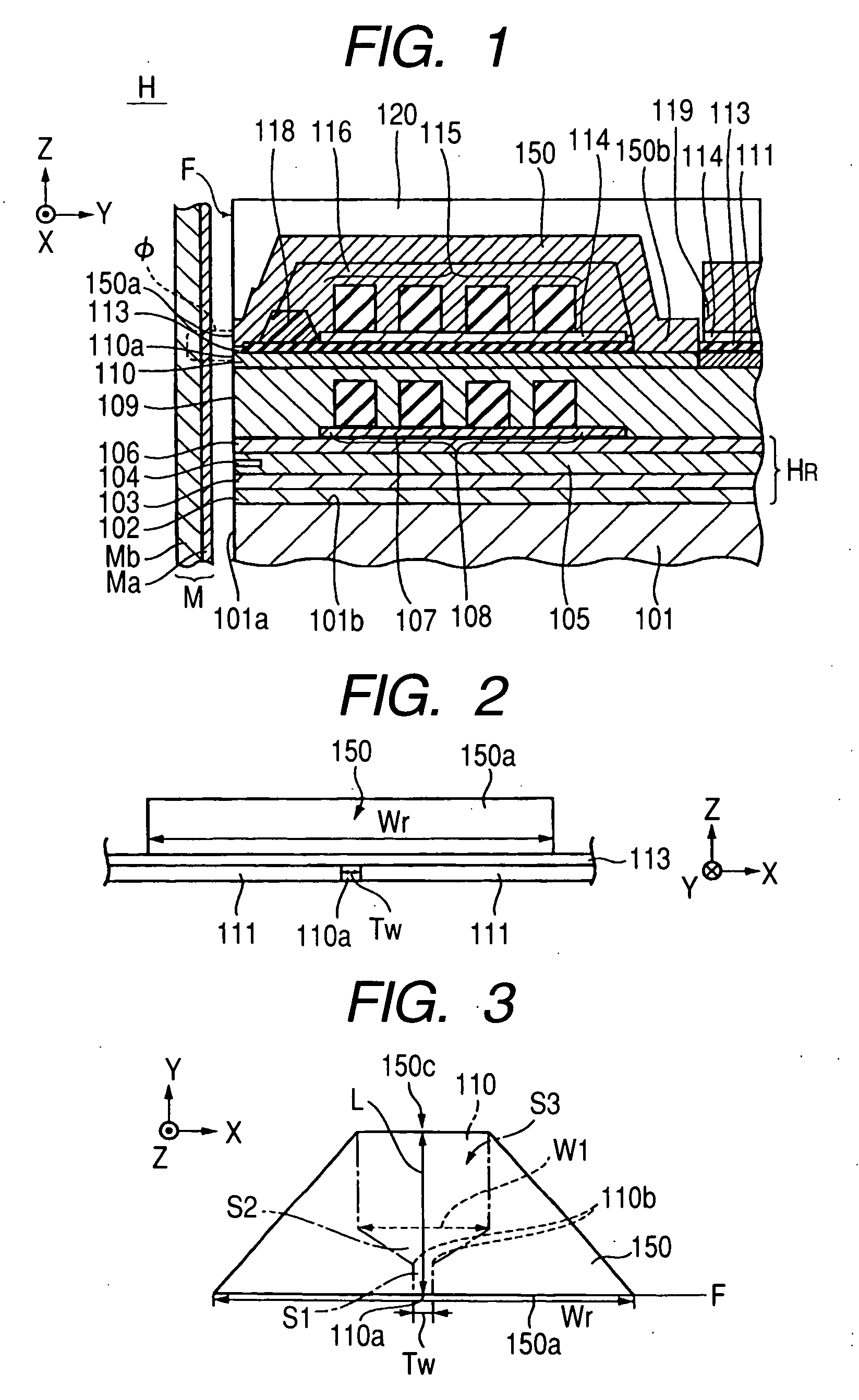
[0034]FIG. 1 is a longitudinal cross-sectional view partially showing an entire configuration of a perpendicular magnetic recording head according to a FIG. 2 is a front view partially showing the perpendicular magnetic recording head, and FIG. 3 is a plan view partially showing the perpendicular magnetic recording head. In FIGS. 1 to 3, an X direction, a Y direction, and a Z direction are defined as a track width direction, a height direction, and a direction where a recording medium M moves, respectively.

[0035] A perpendicular magnetic recording head H applies a perpendicular magnetic field to the recording medium M so that a hard film Ma of the recording medium M is magnetized in a direction perpendicular to the hard film. The recording medium M includes the hard film Ma and a soft film Mb. The hard film Ma has a high residual magnetization and is provided close to the surface of the recording medium M, and the soft film Mb has a high magnetic transmittance and is provided at an...

second embodiment

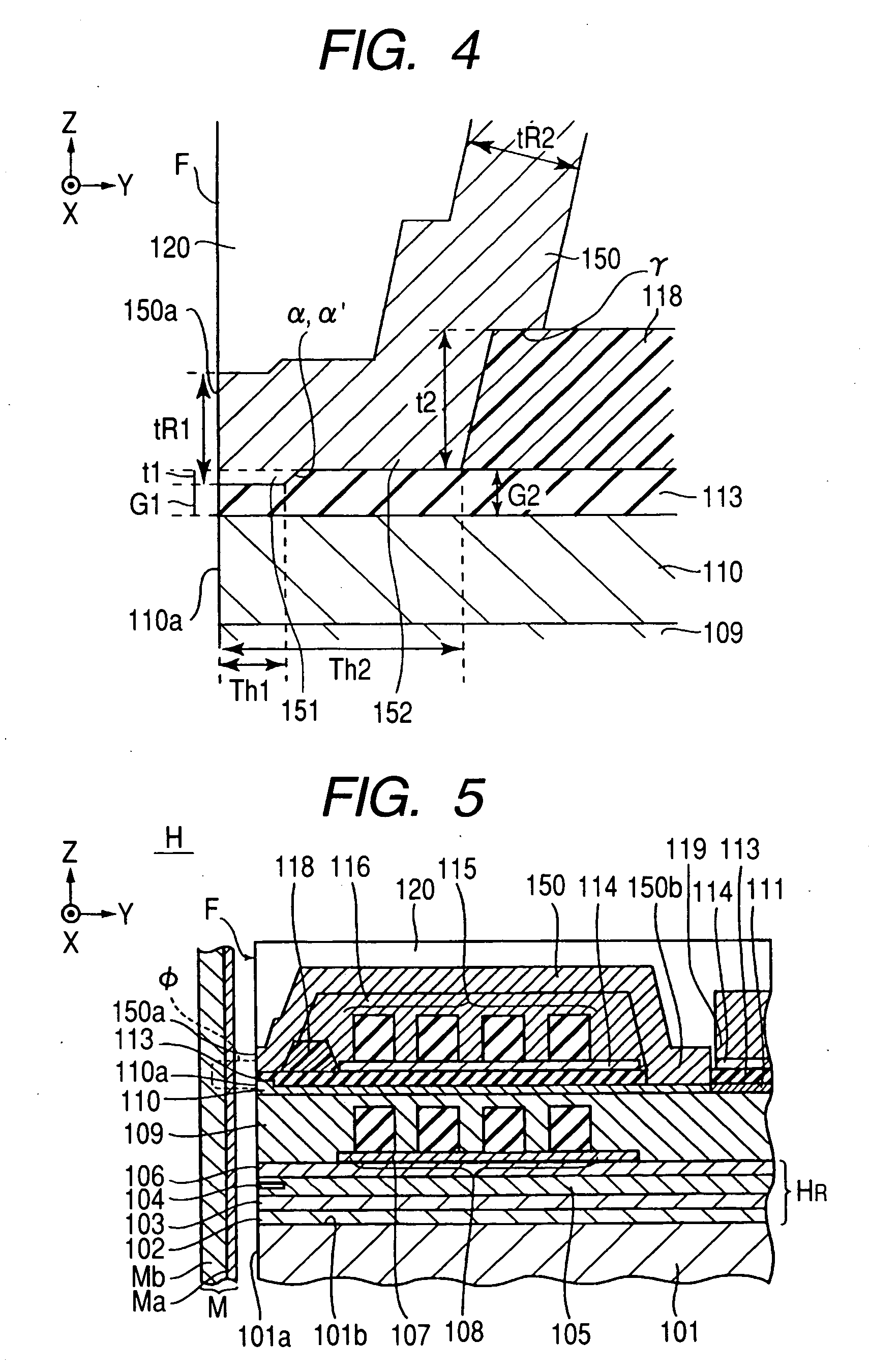
[0064]FIGS. 5 and 6 show a perpendicular magnetic recording head according to a FIG. 5 is a longitudinal cross-sectional view partially showing the entire configuration of the perpendicular magnetic recording head, and FIG. 6 is an enlarged cross-sectional view showing a recording part (a main magnetic pole layer 110, a gap layer 113, and a return path layer 150) near a medium facing surface F.

[0065] According to the second embodiment, the main magnetic pole layer 110 is provided with a stepped portion so that the distance (gap) between the main magnetic pole layer 110 and the return path layer 150 at the rear in the height direction is larger than that at a position close to the medium facing surface F. The second embodiment has the same configuration as the first embodiment except for the main magnetic pole layer 110, the gap layer 113, and the return path layer 150. In FIGS. 5 and 6, elements having the same functions as those of the first embodiment have the same reference nume...

third embodiment

[0074] In the third embodiment, the depth from the front end surface 110a of the main magnetic pole layer 110 to the stepped portion β is equal to the depth of the first throat portion 151 of the return path layer 150, and is represented as a first throat height Th1. The depth of the second throat portion 152 of the return path layer 150 is represented as a second throat height Th2. It is possible to appropriately set the position of the stepped portion α′, and to set the position of the stepped portion α of the return path layer 150 to be different from that of the stepped portion β of the main magnetic pole layer 110.

[0075] The thickness t6 of the gap layer 113 at the rear in the height direction is larger than the thickness t5 thereof at a position close to the medium facing surface F. The thickness t5 of the gap layer 113 at a position close to the medium facing surface F corresponds to a first gap G1, and the thickness t6 of the gap layer 113 at the rear in the height direction...


PUM

PropertyMeasurementUnit
distanceaaaaaaaaaa
lengthaaaaaaaaaa
lengthaaaaaaaaaa

Abstract

A magnetic recording head and a method of manufacturing the magnetic recording head are provided. The perpendicular magnetic recording head includes a main magnetic pole layer and a return path layer that face each other with a gap therebetween in a lamination direction. A non-magnetic insulating layer is interposed between the main magnetic pole layer and the return path layer. At least one stepped portion is formed on a facing surface of at least one of the main magnetic pole layer and the return path layer.

Description

[0001] This application claims the benefit of Japanese Patent Application No. 2005-275558 filed on Sep. 22, 2005, which is hereby incorporated by reference. BACKGROUND [0002] 1. Field [0003] The present embodiments relate to a perpendicular magnetic recording head and a method of manufacturing the perpendicular magnetic recording head. [0004] 2. Related Art [0005] Generally, a magnetic head device includes a longitudinal recording (in-plane recording) magnetic head device that applies a magnetic field parallel to a recording medium thereto to perform a recording operation, and a perpendicular magnetic recording head device that applies a magnetic field perpendicular to a recording medium thereto to perform a recording operation. The perpendicular magnetic recording head device is further suitable to increase the recording density. [0006] As commonly known, the perpendicular magnetic recording head has a structure in which a main magnetic pole layer and a return path layer are lamina...

Claims


Application Information

Patent Timeline
Patent Type & Authority Applications(United States)
IPC IPC(8): G11B5/127
CPCG11B5/1278G11B5/3116G11B5/1871
Inventor YAZAWA, HISAYUKIWATANABE, TOSHINORI
Owner TDK CORPARATION
Why Eureka
Try Eureka