Optical disc apparatus

a technology of optical discs and optical discs, which is applied in the field of optical disc apparatuses, can solve the problems of difficult to avoid collision between the objective lens and the optical disc completely, deterioration of the optical properties of the objective lens or the optical disc, and instantaneous heavy damage or hitting of traces, so as to improve the long-time reliability of recorded data, the effect of low cost and simple and easy upgrad

Inactive Publication Date: 2007-03-22
PANASONIC CORP
View PDF6 Cites 6 Cited by
  • Summary
  • Abstract
  • Description
  • Claims
  • Application Information

AI Technical Summary

Benefits of technology

[0023] In the optical disc apparatus of the present invention, since not only the objective lens never collides with the optical disc even when servo operation is not being performed but the optical disc is not damaged even under strong disturbances, long-time reliability of recorded data can be upgraded simply and easily at low cost.
[0024] Meanwhile, in the optical disc apparatus of the present invention, information to be recorded or reproduced is recorded or reproduced at a rate higher than a data rate of the information so as to produce an inactive duration of the recording or the reproduction and a means for withdrawing the objective lens to a position distant from the optical disc during this inactive duration is provided. Thus, even if external vibrations or impacts are applied to the optical disc apparatus, collision of the objective lens with the optical disc can be prevented, so that it is possible to prevent unstable recording and reproducing operations due to damage to the optical disc caused by the collision. Therefore, portability and power saving of the optical disc apparatus can be further enhanced.

Problems solved by technology

In such a small working distance, a problem arises that it is basically difficult to avoid collision between the objective lens and the optical disc completely.
Therefore, in a state where servo operation is not being performed, contact between the objective lens and the optical disc may happen a number of times during a short period, thereby possibly resulting in heavy damage or hitting traces instantaneously.
As a result, deterioration of optical properties of the objective lens or the optical disc may pose a problem in recording and reproduction.

Method used


Image

  • Optical disc apparatus
  • Optical disc apparatus
  • Optical disc apparatus

Examples


first embodiment

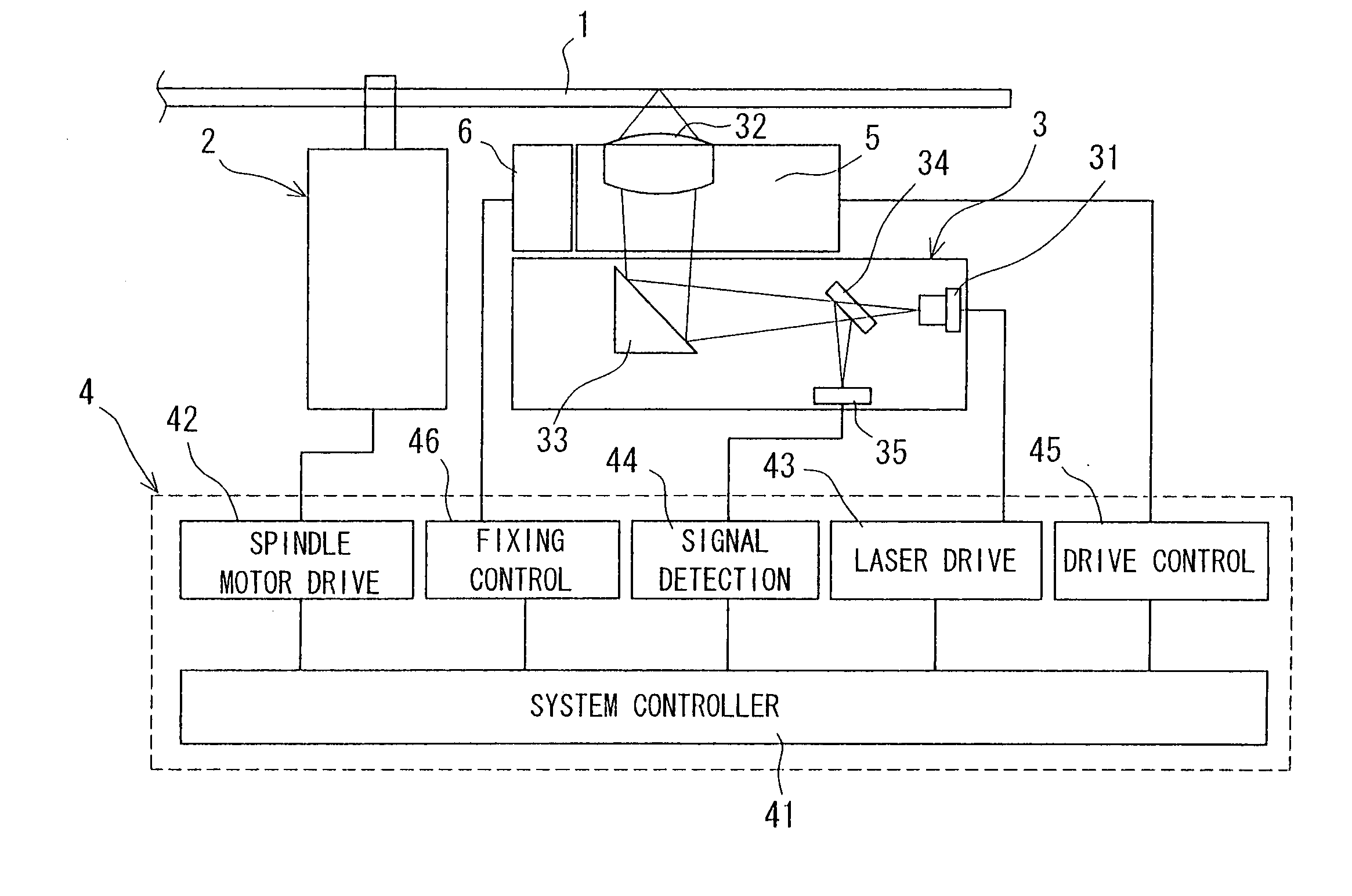
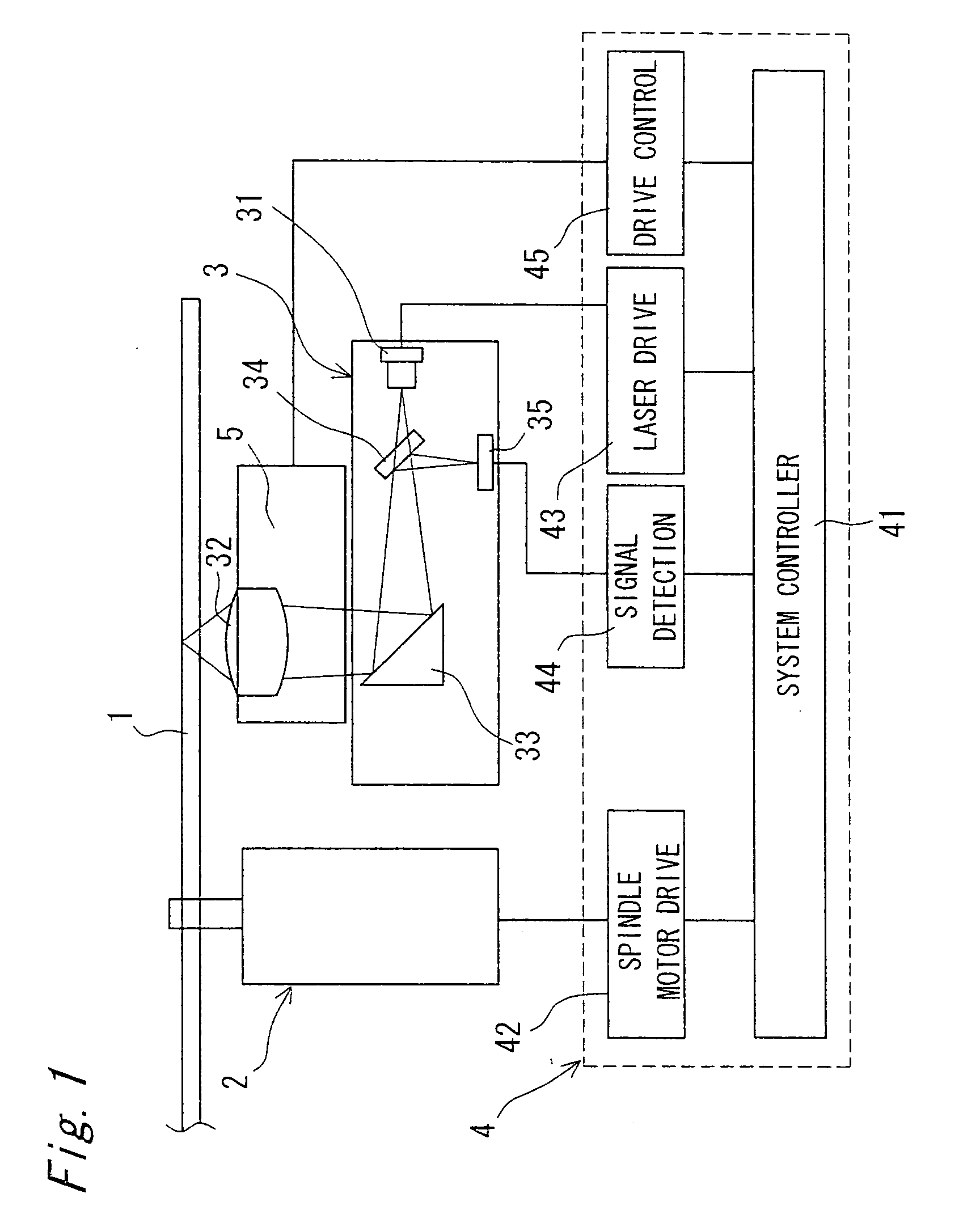
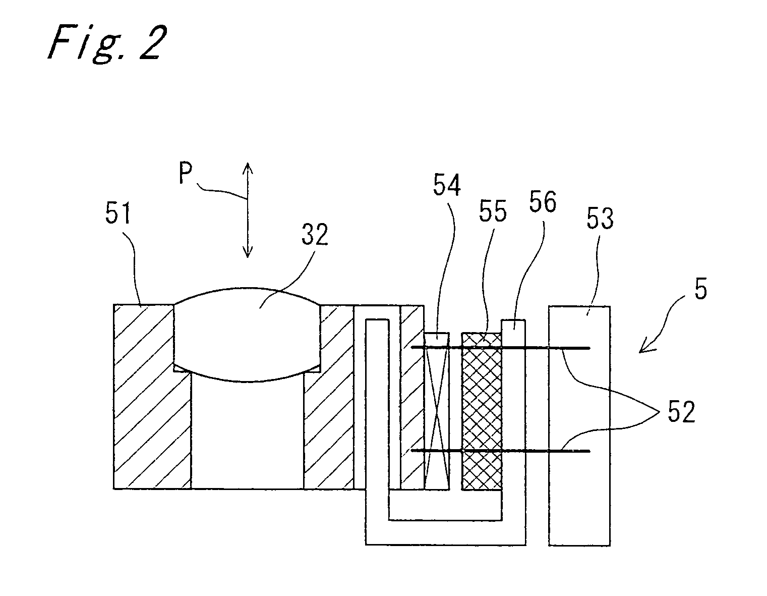
[0037]FIG. 1 shows a schematic structure of an optical disc apparatus according to a first embodiment of the present invention and FIG. 2 shows a schematic structure of an objective lens actuator 5 of this optical disc apparatus on an enlarged scale. As shown in FIG. 1, the optical disc apparatus of the first embodiment is roughly divided into a spindle motor (rotational drive portion) 2 for rotating an optical disc 1, an optical head 3 for recording or reproducing information on the optical disc 1 by illuminating a beam onto the optical disc 1 and a drive circuit 4 for controlling operation of the spindle motor 2 and the optical head 3. An objective lens actuator 5 is mounted on the optical head 3.

[0038] The optical head 3 includes a laser 31 for emitting a beam, an objective lens 32 for illuminating onto the optical disc 1 the beam emitted from the laser 31, a mirror 33 for changing towards the objective lens 32 a direction of the beam emitted from the laser 31, a beam splitter 3...

second embodiment

[0046] Hereinafter, a second embodiment of the present invention is described concretely. FIGS. 3 and 4 schematically show an optical disc apparatus according to the second embodiment. This optical disc apparatus is has an arrangement fundamentally similar to that of the optical disc apparatus according to the first embodiment of FIGS. 1 and 2 and like parts are designated by like reference numerals in the first and second embodiments.

[0047] As is clear from FIG. 3, its differences from the first embodiment of FIGS. 1 and 2 reside in that additionally, an objective lens fixture 6 for fixing the objective lens 32 is provided on the optical head 3 and at a side of the objective lens actuator 5 and a fixing control circuit 46 for controlling the objective lens fixture 6 is provided in the drive circuit 4. As shown in FIG. 4, the objective lens fixture 6 includes a drive portion 61 formed by a stepper or a piezoelectric element and a stopper 62 which is displaced in the direction of th...

third embodiment

[0053]FIGS. 6A to 6C show a schematic structure of an optical disc apparatus according to a third embodiment of the present invention. FIG. 7 shows changes of planar deflection of the optical disc 1 with time in the optical disc apparatus of FIG. 6. The planar deflection of the optical disc 1 can be substantially approximated to a sine curve and has an amplitude (±A) from an average plane “0”. In the same manner as in prior art, a working distance WD set, for the objective lens 32, between the optical disc 1 and the objective lens 32 is smaller than the amplitude (2A) of the planar deflection of the optical disc 1, namely, WD<2A.

[0054] A lens holder 72 acting as the support members is formed by, for example, a tubular member and secures the objective lens 32 such that the objective lens 32 is brought into alignment with the lens holder 72. At this time, on one face of the lens holder 72 confronting the optical disc 1, a protective ring 72a for protecting the objective lens 32 is in...


PUM

PropertyMeasurementUnit
sizeaaaaaaaaaa
electricaaaaaaaaaa
resonant frequencyaaaaaaaaaa

Abstract

An optical disc apparatus includes a withdrawal means for moving an objective lens (32) to a position distant from an optical disc (1) during an inactive duration of intermittent recording or reproducing operation. A means for regulating or fixing the objective lens (32) at the position distant from the optical disc (1) is further provided. Thus, even in a noncontrolled state during the inactive duration, it is possible to prevent collision of the objective lens (32) with the optical disc (1). As a result, both power saving and safety of the apparatus can be attained.

Description

TECHNICAL FIELD [0001] The present invention relates to optical disc apparatuses for recording or reproducing audio and images or recording or reproducing various data for computers, etc. For example, the present invention relates to an optical disc apparatus of a portable type, which has a function of operating intermittently in order to reduce its power consumption. BACKGROUND ART [0002] In response to recent trends to more compact optical disc apparatuses, portable optical disc apparatuses operating on batteries have come into general use. In this connection, various proposals are made on technology of so-called “intermittent operation” designed to reduce power consumption of the optical disc apparatuses for the purpose of increasing operating time of the batteries. [0003] For example, a first prior art document Japanese Patent Laid-Open Publication No. 5-342585 (1993) discloses a basic idea in which data is recorded or reproduced at a rate higher than a data rate of information ...

Claims


Application Information

Patent Timeline
Patent Type & Authority Applications(United States)
IPC IPC(8): G11B7/00G11B7/085G11B7/09G11B7/12G11B7/125
CPCG11B7/08576G11B7/085
Inventor MIZUNO, OSAMUNAKAMURA, TOHRUAIKOH, HIDEKIHAYASHI, TAKAOWADA, TAKUYA
Owner PANASONIC CORP
Why Eureka
Try Eureka