Consumer equipment remote operation system and operating method for the same

a technology for operating systems and consumer equipment, applied in the direction of digital transmission, data switching networks, instruments, etc., can solve the problems of large burden on users, difficult for users to access and operate home equipment from the exterior,

Inactive Publication Date: 2007-03-22
KDDI CORP
View PDF3 Cites 65 Cited by
  • Summary
  • Abstract
  • Description
  • Claims
  • Application Information

AI Technical Summary

Benefits of technology

[0010] An object of this invention is provide a consumer equipment remote operation system and a method for putting this system into operation that enables consumer equipments to be configured automatic

Problems solved by technology

It was thus difficult for a user to access and operate home equipments from the exterior.
However, a computer is generally necessary for confi

Method used


Image

  • Consumer equipment remote operation system and operating method for the same
  • Consumer equipment remote operation system and operating method for the same
  • Consumer equipment remote operation system and operating method for the same

Examples


second embodiment

[0068] As this invention, procedures from detection of a UPnP-disabled consumer equipment to registration of equipment information and deletion of the equipment information shall be described with a reference to the sequence diagram of FIG. 9.

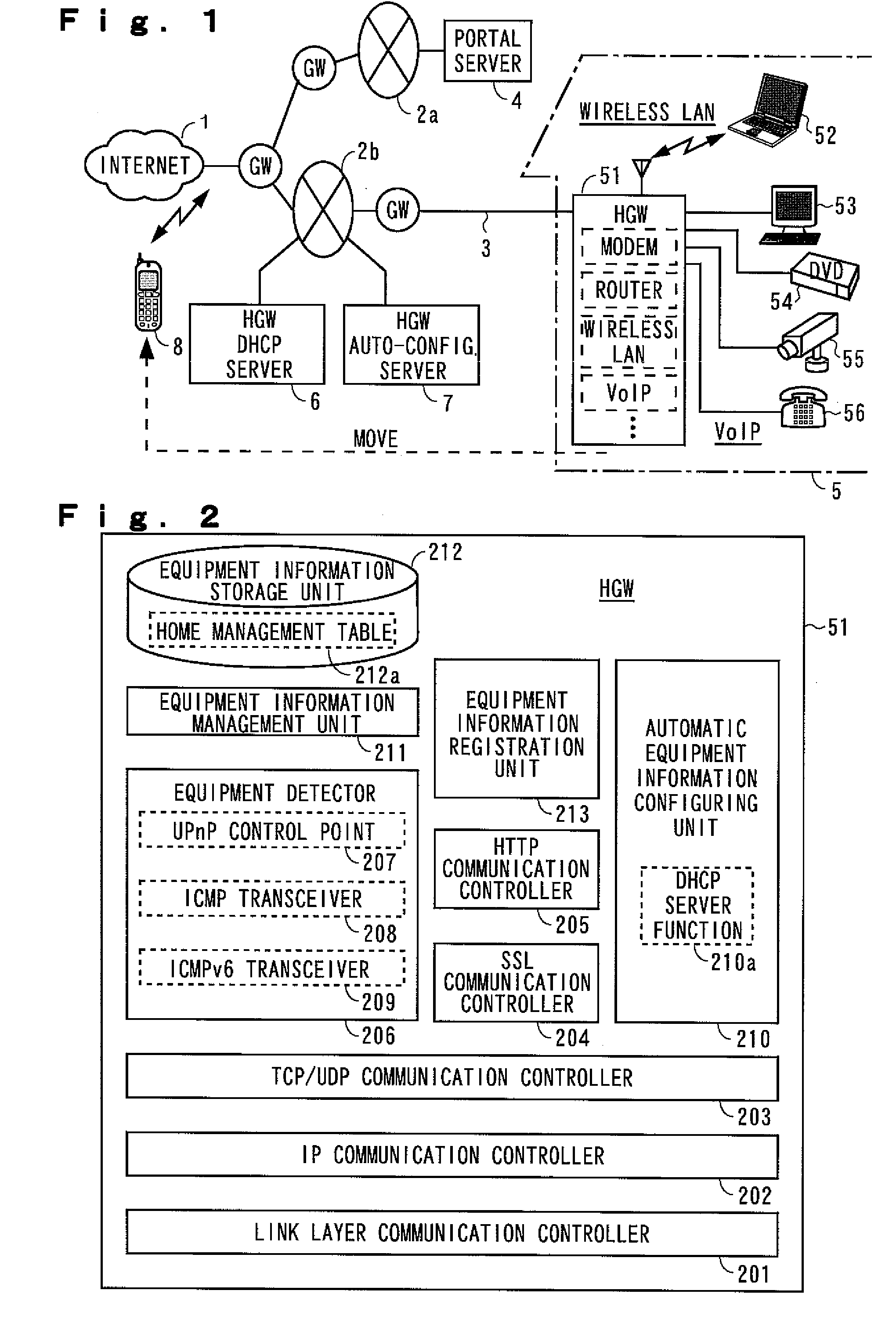
[0069] After the HGW 51 is started up in step S31 and after network configuration of the UPnP-disabled IPv4 equipment by DHCP is performed, an ICMP (Internet Control Message Protocol) ECHO request is transmitted cyclically from the ICMP transceiver 208 to a preset IPv4 address range set in step S32. The address range is set, for example, by designating a search head address, such as “192.168.0.2,” and a search range, such as “6,” and in this case, the ICMP ECHO request is transmitted successively to the respective addresses of six units from “192.168.0.2” to “192.168.0.7.” If a piece of IPv4-enabled consumer equipment is connected to the home network, an ICMP ECHO response is transmitted back from the consumer equipment and this is received by ...

third embodiment

[0080] As this invention, procedures from detection of a UPnP-disabled IPv6 consumer equipment to registration of equipment information and deletion of the equipment information shall be described with reference to the sequence diagram of FIG. 12.

[0081] After the HGW 51 is started up in step S51, an ICMPv6 ECHO request is broadcast-transmitted (with the destination address being FF02::1) cyclically from the ICMPv6 transceiver 209 in step S52. If an IPv6-enabled consumer equipment is connected to the home network, an ICMPv6 ECHO response is transmitted back from the consumer equipment in step S53. This response message is received by the ICMPv6 transceiver 209 and a link local IPv6 address is acquired. In step S54, an interface ID is extracted from the acquired link local IPv6 address and is joined with the IPv6 Prefix provided to the HGW 51 to generate a global IPv6 address of the responding IPv6 equipment.

[0082] For example, if the IPv6 Prefix provided to the HGW 51 is 3FFE:0000:0...


PUM


Abstract

By simply connecting consumer equipments physically to a home network, configurations are set automatically for the consumer equipment, and the consumer equipment is enabled to be remote operated easily via a home gateway that is not necessarily fixed in address.
A home gateway 51 includes: a home management table 212a that manages equipment information of consumer equipment connected to the home network; an equipment detector 206 that cyclically transmits a detection request along the home network, detects consumer equipment, and acquires the equipment information of the detected consumer equipment; an equipment management unit 211 that updatingly registers the equipment information of the detected consumer equipment into the above-described home management table 212a; a DHCP server function 210a that sets network configurations for newly detected consumer equipment; and an equipment information registration unit that updatingly registers the equipment information in the home management table cyclically into a portal server 4.

Description

BACKGROUND OF THE INVENTION [0001] 1. Field of the Invention [0002] This invention is targeted at a home network that is already provided with an ADSL (Asymmetric Digital Subscriber Line), an optical fiber line, or other communication line that is constantly connected to the Internet. This invention relates to a consumer equipment remote operation system that enables configurations to be set automatically upon simply connecting a network camera, DVD recorder, or other network-ready consumer equipment physically to the home network and without using a computer and enables remote operation of the consumer equipment via the network from a terminal inside or outside a home, and also relates to a method for putting this system into operation. [0003] 2. Description of the Related Art [0004] Remote operation systems, with which a network-ready DVD recorder, network camera, and other consumer equipments are connected to a home network in advance and, upon setting various configurations, the...

Claims


Application Information

Patent Timeline
IPC IPC(8): G06F15/173
CPCH04L12/2602H04L12/2803H04L12/2809H04L12/281H04L12/2818H04L29/12226H04L67/025H04L41/0886H04L41/12H04L43/00H04L43/0811H04L43/0817H04L61/2015H04L41/082H04L61/5014
Inventor YOSHIHARA, KIYOHITOMOTEGI, SHINJIHORIUCHI, HIROKI
Owner KDDI CORP
Why Eureka
Try Eureka