
Bottom assembly for an article of footwear

a technology of bottom assembly and footwear, which is applied in the direction of fastenings, applications, domestic applications, etc., can solve the problems of increasing the risk of accidents, reducing increasing the gripping effect. , to achieve the effect of improving the adaptability of the elastically deformable element, preventing any risk of sudden tilting, and noticing the increase of gripping

Inactive Publication Date: 2007-03-29
SALOMON SA
View PDF16 Cites 11 Cited by
  • Summary
  • Abstract
  • Description
  • Claims
  • Application Information

AI Technical Summary

Benefits of technology

[0017] An object of the present invention is to overcome the aforementioned drawbacks, and to provide an article of footwear, particularly a running shoe, having a bottom assembly adapted for making it possible to improve the grip of the shoe on a hilly, sloping, slanting terrain, and which also allows for a better adaptation to the unevenness and irregularities of the terrain.
[0018] Another object of the present invention is to provide a more stable shoe or article of footwear.
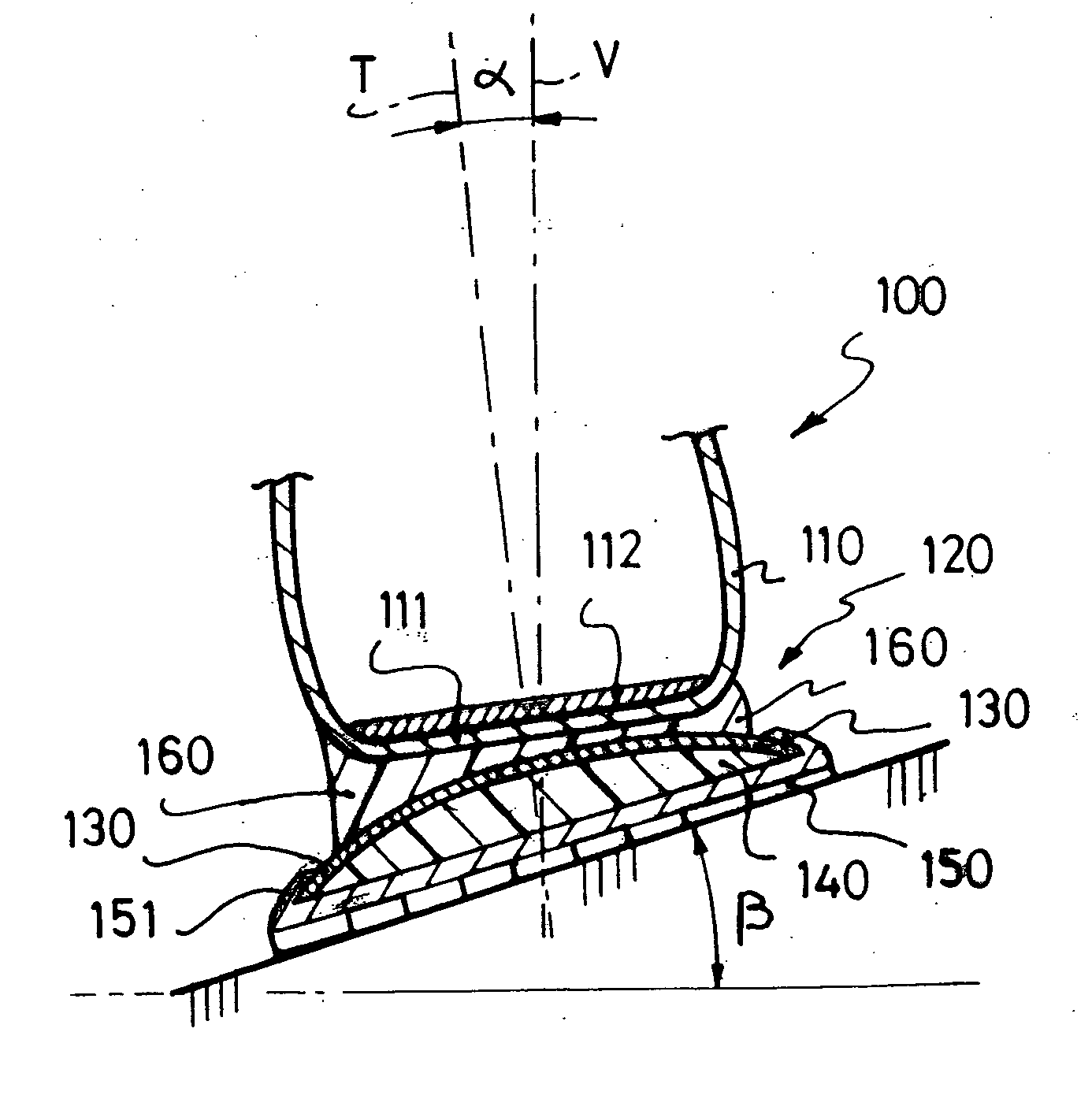
[0021] Indeed, the arch-shaped or vault-shaped elastically deformable element makes it possible to directly carry the forces imposed by the wearer over to the medial, lateral edge, respectively, of the outsole, and therefore to increase the gripping effect noticeably, compared to a shoe of the conventional type where the forces are uniformly transmitted, even on a sloping terrain.
[0022] Furthermore, the deforming ability of the elastically deformable element enables the bottom assembly to deform in a progressive and continuous manner, in the case of a medial or lateral bending, and prevents any risk of sudden tilting that could cause injuries (sprains, etc.).
[0023] According to one embodiment, the elastically deformable element has on each side at least one medial, lateral arm, respectively. The provision of independent lugs or arms further improves the adaptability of the elastically deformable element to the terrain and to the various roughness / unevenness thereof, and therefore makes it possible to guarantee an optimal stability of the entire shoe, irrespective of the type of terrain.

Problems solved by technology

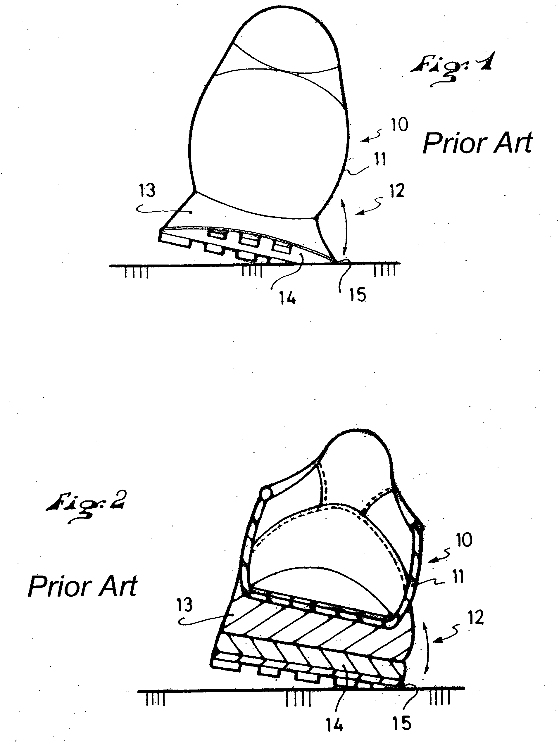
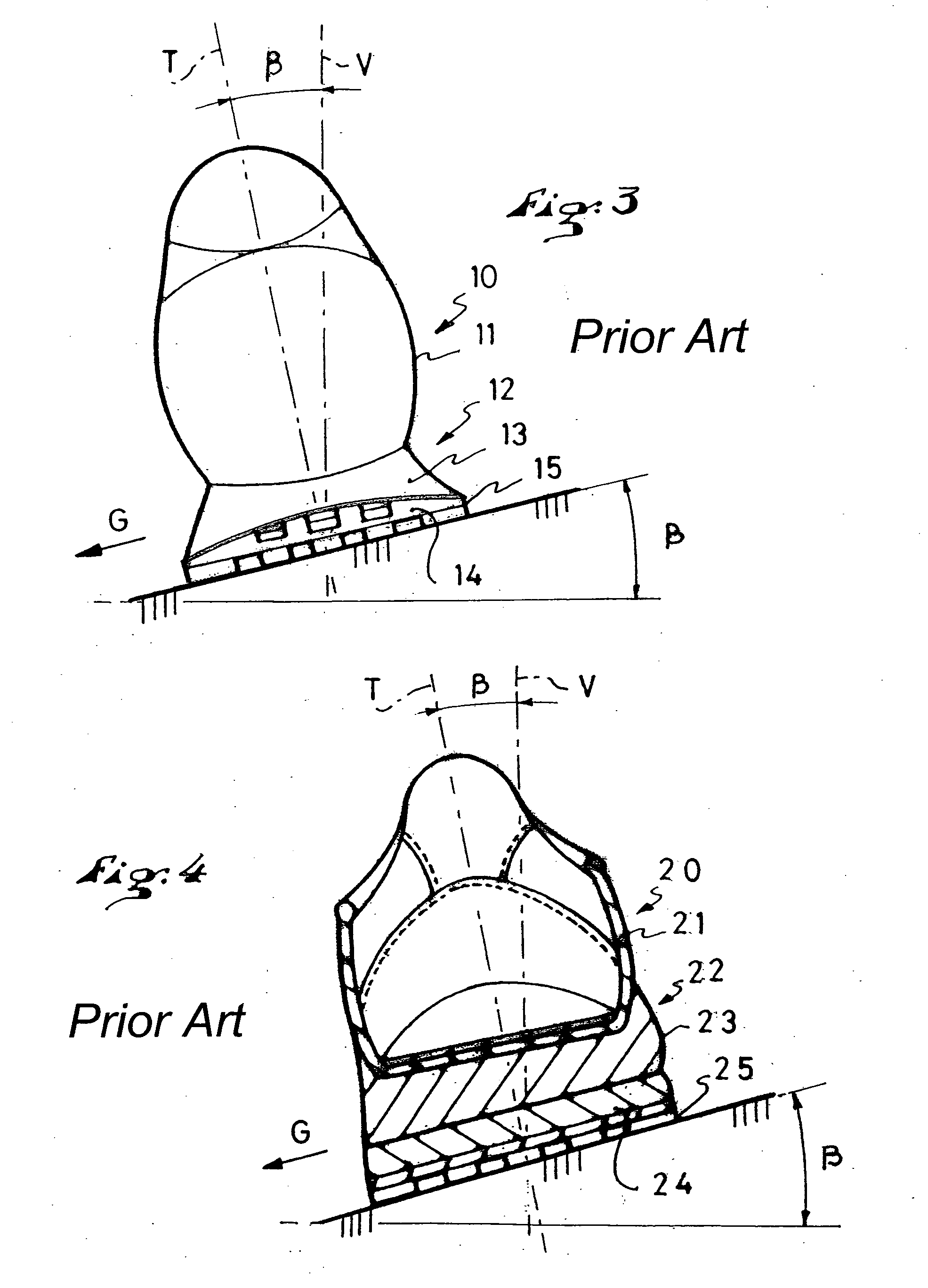
FIGS. 1-4 illustrate problems related to the use of conventional shoes for running, especially in the mountains or uneven terrain.
Once this midsole 13 is completely compressed, the shoe tends to tilt suddenly in relation to its edge 15 and can then cause injuries (sprains, etc.).
However, this second type of shoe has the same drawback of sudden tilting once the layer of the midsole 13 is completely compressed.
However, the development of sporting contests of the “raid” type, including various sporting activities taking place in a mountainous environment, and including foot races in the mountains, in particular, involve new constraints on the shoes and the users.
Because only few running shoes actually provided for such conditions are commercially available, there are numerous traumatic problems and risks of accidents for the runners.

Method used


Image

  • Bottom assembly for an article of footwear
  • Bottom assembly for an article of footwear
  • Bottom assembly for an article of footwear

Examples


first embodiment

[0039]FIGS. 5 and 6 show, by means of a schematic transverse cross-section in the heel area, a shoe 100 according to the invention. This shoe 100 has an upper 110 provided with an inner sole or insole 112, and a bottom assembly 120.

[0040] Although the term shoe is used herein for convenience, such use is not intended to limit the invention otherwise described herein, which invention is intended to encompass articles of footwear not specifically illustrated, such as those having uppers that extend above the ankle, for example, as well as those having uppers that rise to the level of the ankle or below the ankle.

[0041] The bottom assembly 120, from top down, includes the following: [0042] a wedge 160 for connecting to the upper 110; [0043] an elastically deformable element 130 that is substantially arch-shaped or vault-shaped in transverse cross-section; [0044] a layer of shock-absorbing material 140; [0045] an outsole or walking sole 150.

[0046] The elastically deformable element 13...

second embodiment

[0064]FIGS. 7, 8, 9, 10 show the invention in which the same elements are designated by the same reference numerals.

[0065]FIGS. 7 and 9 particularly show the stacking of the various layers of the bottom assembly in the heel zone, namely: [0066] outsole 150; [0067] shock-absorbing material 140; [0068] elastically deformable element 130; [0069] connecting member or wedge 160.

[0070] Furthermore, in this embodiment, the upper 110 is provided with an outer heel stiffener 115 adapted to procure more stability to the foot and to better transmit the force of the foot to the ground via the elastically deformable element 130. This heel stiffener 115 is preferably made of a rigid synthetic or composite material, and is selected so as to have a Young's modulus E greater than 40 Mpa, or greater than approximately 40 Mpa. It is assembled to the upper 110 either at the time of positioning the bottom assembly 120, or prior to that. This stiffener 115 can be recessed as shown in FIG. 9, i.e., surro...


PUM

PropertyMeasurementUnit
widthaaaaaaaaaa
widthaaaaaaaaaa
widthaaaaaaaaaa

Abstract

An article of footwear having an upper and an outer bottom assembly, the outer bottom assembly having an outsole and, in the heel zone, an elastically deformable element that extends downward from the lower end of the upper to the medial, lateral edges, respectively, of the outsole.

Description

CROSS-REFERENCE TO RELATED APPLICATIONS [0001] This application is a continuation of U.S. patent application Ser. No. 10 / 773,284, which had been filed on Feb. 9, 2004 and published on Sep. 2, 2004 as U.S. Pat. No. 2004 / 0168350, the disclosure of which is hereby incorporated by reference thereto in its entirety, and the priority of which is hereby claimed under 35 U.S.C. §120. [0002] This application is based upon French Patent Application No. 03.01899, filed Feb. 14, 2003, the disclosure of which is hereby incorporated by reference thereto in its entirety and the priority of which is hereby claimed under 35 U.S.C. §119.BACKGROUND OF THE INVENTION [0003] 1. Field of the Invention [0004] The invention relates to an article of footwear, i.e., a boot or shoe, for example, that is adapted for use for walking or running, particularly over mountainous terrain. More particularly, the invention relates to a sole or bottom assembly designed for such an article of footwear. [0005] 2. Descripti...

Claims


Application Information

Patent Timeline
Patent Type & Authority Applications(United States)
IPC IPC(8): A43B13/14A43B13/18A43B1/10A43B5/00A43B13/12A43C15/09
CPCA43B3/0036A43B5/002A43B13/026A43B7/144A43B13/125A43B13/146A43C15/09A43B13/12A61K8/0208A47K10/16
Inventor MATHIEU, GUILLAUMECHALLE, JEAN-MICHEL
Owner SALOMON SA
Learn More