
Equipment for insertion of objects into smoking articles

Active Publication Date: 2007-03-29
R J REYNOLDS TOBACCO COMPANY
View PDF89 Cites 223 Cited by
  • Summary
  • Abstract
  • Description
  • Claims
  • Application Information

AI Technical Summary

Benefits of technology

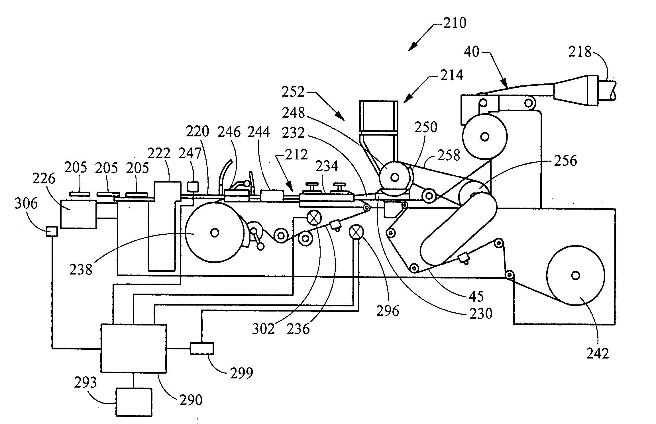
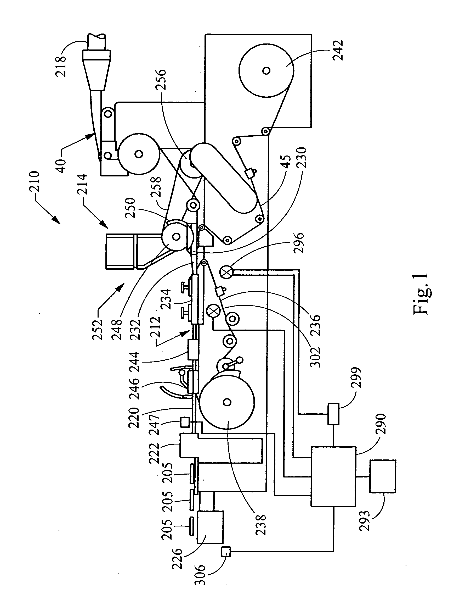
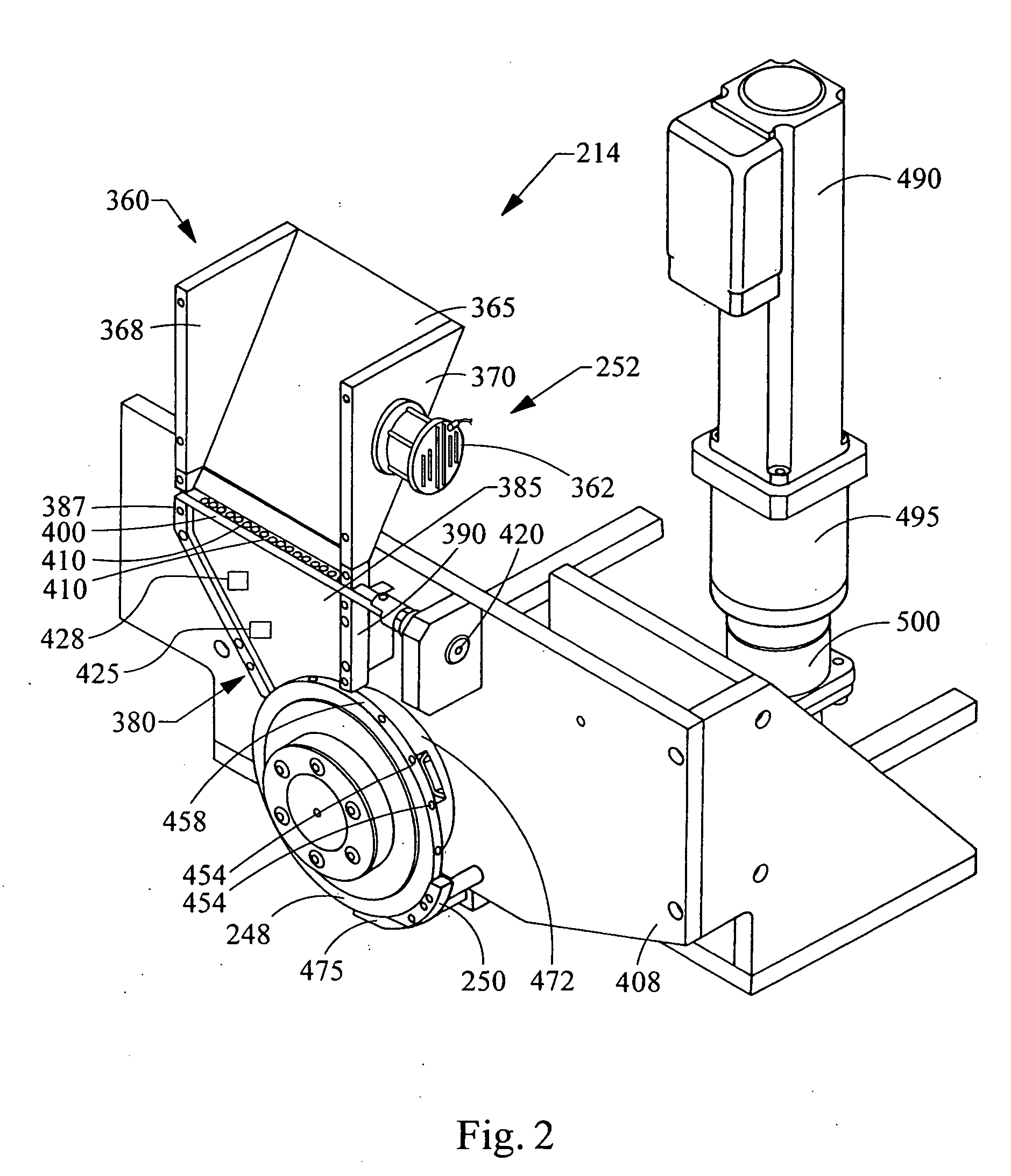
[0013] The peripheral face of the rotating wheel incorporates a plurality of spaced pockets, each pocket being of sufficient shape and size to accommodate one object. Individual objects are placed into individual pockets located at pre-determined intervals on the peripheral face of the rotating wheel. Vacuum applied to each pocket acts to assist in ensuring that each pocket accepts an object, and that each object within a pocket is maintained in that pocket during transport. Each object then is positioned at predetermined intervals within a continuous supply of filter material. Air pressure applied to each pocket acts to blow that object out of the pocket at the desired time (e.g., when the object carried by the rotating wheel is located at the desired location within the continuous supply of filter material. Then, the filter material is formed into a continuous rod having individual objects positioned at predetermined spaced intervals within that rod. The continuous rod then is subdivided at predetermined intervals so as to form a plurality of filter rods (e.g., four-up filter rods containing four spaced objects).

Problems solved by technology

Because certain agents that can be used to interact with smoke are volatile and have the propensity to evaporate over time, the effects of those agents upon the behavior of those cigarettes may require introduction of those agents near commencement of the smoking experience.

Method used


Image

  • Equipment for insertion of objects into smoking articles
  • Equipment for insertion of objects into smoking articles
  • Equipment for insertion of objects into smoking articles

Examples


Embodiment Construction

[0027] The production of filter rods, filter rod segments and filter elements, and the manufacture of cigarettes from those filter rods, filter rod segments and filter elements can be carried out using the types of rod-forming units that have been employed to provide cigarette filters, multi-segment cigarette filters and filtered cigarettes. Multi-segment cigarette filter rods can be manufactured using a cigarette filter rod making device available under the brand name Mulfi from Hauni-Werke Korber & Co. KG of Hamburg, Germany. Other representative types of commercially available filter rod making equipment that can suitably modified for use include the KDF-2 unit available from Hauni-Werke Korber & Co. KG and the Decoufle unit available from Decoufle of France.

[0028] Cigarettes made by the apparatus of the present invention are manufactured using filter elements provided from filter rods. Six-up filter rods, four-up filter rods and two-up filter rods that are conventionally used f...


PUM


Abstract

Apparatus incorporating a filter tow processing unit adapted to supply filter tow to a continuous rod forming unit includes an object insertion unit that positions objects within the filter tow to manufacture a filter rod containing objects positioned at predetermined intervals. The apparatus also includes an upper hopper that acts as a reservoir for a plurality of objects, and provides for supply of objects to a lower hopper. The lower hopper is shaped so that objects are stacked therein. The bottom of the lower hopper is shaped so as to cooperate with a portion of upper region of a rotating wheel. The peripheral face of the rotating wheel incorporates a plurality of spaced pockets, each pocket being of sufficient shape and size to accommodate one object. Objects within the lower hopper are aligned in a single line along a portion of the peripheral face in the upper region of the rotating wheel. Each object then is positioned at predetermined intervals within a continuous supply of filter material. Then, the filter material is formed into a continuous rod having individual objects positioned at predetermined spaced intervals within that rod. The continuous rod then is subdivided at predetermined intervals so as to form a plurality of filter rods (e.g., four-up filter rods containing four spaced objects).

Description

FIELD OF THE INVENTION [0001] The present invention relates to apparatus and methods for manufacturing smoking articles and components of smoking articles, such as filter elements. In particular, the present invention relates to apparatus for inserting objects into a filter component for use in the manufacture of a filter element for a smoking article, such as a cigarette. BACKGROUND OF THE INVENTION [0002] Popular smoking articles, such as cigarettes, have a substantially cylindrical rod shaped structure and include a charge, roll or column of smokable material such as shredded tobacco (e.g., in cut filler form) surrounded by a paper wrapper thereby forming a so-called “smokable rod” or “tobacco rod.” Normally, a cigarette has a cylindrical filter element aligned in an end-to-end relationship with the tobacco rod. Typically, a filter element comprises cellulose acetate tow plasticized using triacetin, and the tow is circumscribed by a paper material known as “plug wrap.” A cigarett...

Claims


Application Information

Patent Timeline
IPC IPC(8): A24C5/47
CPCA24D3/0216A24D3/061A24D3/0229Y10S493/941A24C5/47A24D3/0295A24D3/0287B31D5/0078B31D2205/0058B31F1/0051
Inventor THOMAS, TIMOTHY FREDERICKBENFORD, ROBERT WILLIAMFAGG, BARRY SMITH
Owner R J REYNOLDS TOBACCO COMPANY
Learn More