Inflatable field enclosure divider

a field enclosure and divider technology, applied in water-skiing, golfing accessories, skiing, etc., can solve the problems of inability to observe the surroundings, may be driven out of the playing area, waste of recreational time, etc., and achieve the effect of improving the efficiency of demarking areas, simple assembly and storage, and convenient deploymen

Inactive Publication Date: 2006-03-14
JAMES DAMIAN ANTHONY
View PDF10 Cites 5 Cited by
  • Summary
  • Abstract
  • Description
  • Claims
  • Application Information

AI Technical Summary

Benefits of technology

[0016]In still another embodiment, the invention is a lightweight, portable, inflatable apparatus for simultaneously substantially enclosing several areas for sports comprising flexible substantially air impervious means for forming a boundary of sufficient size and shape to simultaneously demark a plurality of areas for sports; and means for connecting said boundary with an air source and for conducting said air into the interior of said boundary member to inflate it. In another embodiment, the apparatus also has means for holding players located on the outer perimeter of the apparatus.
[0017]An imp

Problems solved by technology

One of the main problems associated with games played on an open field is that the ball, which is used in the game, may be driven out of the playing area.
Recreational time is wasted as players or coaches seek to retrieve a ball which has escaped a marked area of play.
Furthermore, children seen to retrieve a ball may not be aware of their surroundings and can wander into a dangerous area such as a parking lot or open road.
Another major problem is that a ball traveling at a high rate of speed beyond the playing area may injure onlookers who may be standing or sitting around the perimeter of the playing area.
Also,

Method used


Image

  • Inflatable field enclosure divider
  • Inflatable field enclosure divider
  • Inflatable field enclosure divider

Examples


Embodiment Construction

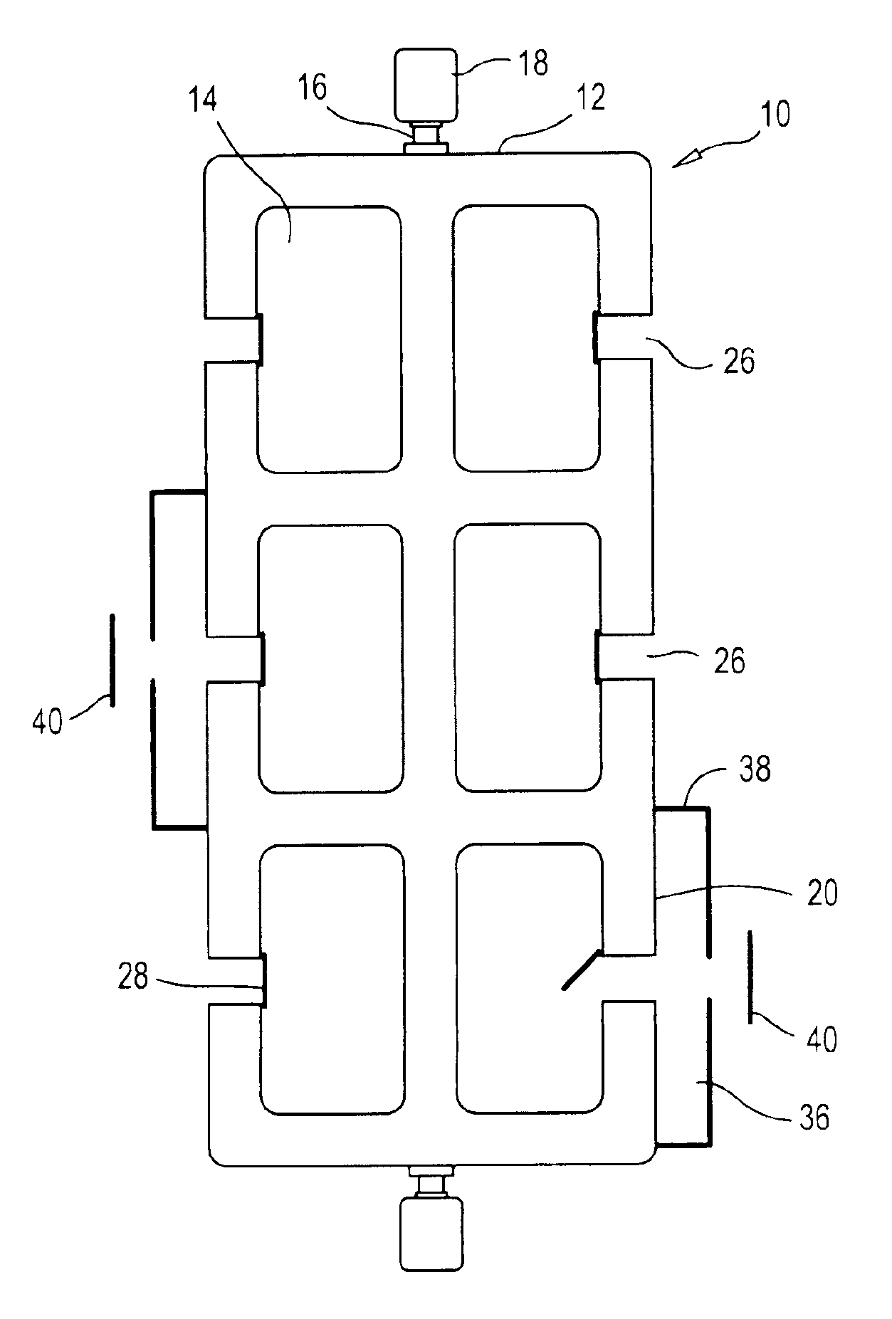
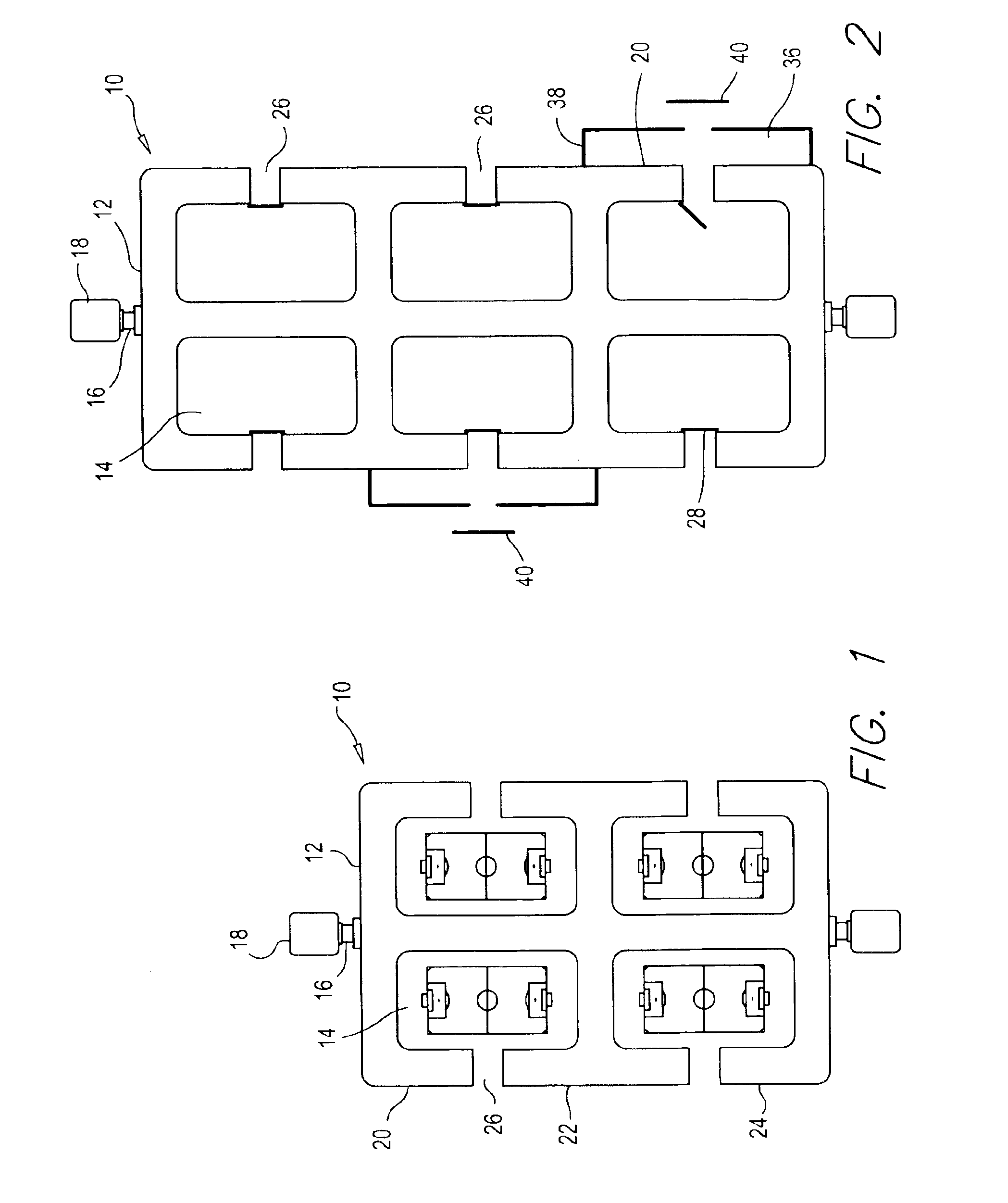
[0032]With respect to the drawings, FIGS. 1-6 depict an inflatable barrier generally indicated by the reference numeral 10. Referring now to FIG. 1, the inflatable barrier 10 of the present invention is shown. The barrier 10 generally comprises an elongated, hollow barrier member 12 formed of connected tubular elements. The elements are hollow and preferably constructed out of flexible substantially fluid impervious material. Preferred materials include vinyl or other air impermeable material, soft plastic, or any other material that can be inflated by a fluid. The term fluid is used herein to include both gasses, such as air, and liquids, such as water. The elements may be joined by glue, paste thread or other binding material that will still enable the member 12 to be put in an inflated state. Alternatively, the member 12 may be formed as a single piece. The member 12 forms a continuous configuration of sufficient size and shape to simultaneously demark several areas 14 for purpos...


PUM


Abstract

An inflatable barrier for simultaneously substantially enclosing several areas comprising an elongated, hollow barrier member formed of connected elements of flexible substantially fluid impervious material joined to form a continuous configuration of sufficient size and shape to simultaneously demark several areas on a substantially flat surface; and a connector to a source of a fluid and for conducting said fluid into the interior of said hollow barrier member to inflate it, said barrier member having at least one interior transverse element and a plurality of end elements for substantially encompassing at least one of the surrounded areas, and said continuous configuration in the inflated condition supported on said substantially flat surface substantially defining a perimeter surrounding said areas. The barrier is capable of holding signage, and includes enclosures for players in an area.

Description

[0001]This application claims the benefit of Provisional Patent Application Ser. No. 60 / 429,934, filed Nov. 29, 2002.BACKGROUND OF THE INVENTION[0002]1. Field of the Invention[0003]The invention related to an inflatable field enclosure. More particularly, it relates to a one-piece system that is easy to assemble and store.[0004]2. Description of Related Art[0005]The need for portable, lightweight, easy to inflate and operate enclosures is varied. For example, conventions or fundraisers need enclosures so different areas can be used for different purposes. However, the need for this type of enclosure for a wide open area is especially sharp in the area of sports.[0006]Many sports are played on a generally open field of a limited size. Opposing teams on the field attempt to drive a ball or similar object into the goal of the opponent. Popular games played on such field include football, soccer, field hockey and rugby, as well as other sports.[0007]One of the main problems associated w...

Claims


Application Information

Patent Timeline
IPC IPC(8): A63B67/00A63B61/00A63C19/00A63B71/02A63C19/08
CPCA63B71/02A63C19/08A63B2225/62A63B2208/12
Inventor JAMES, DAMIAN ANTHONY
Owner JAMES DAMIAN ANTHONY
Why Eureka
Try Eureka