[0017] Another
advantage of the present invention is related to the behavior of the resonant condition which occurs in the
system. The
evanescent mode in a properly designed applicator
system according to the invention becomes inherently resonant, since the excess capacitive energy of the
evanescent mode in the applicator is offset by both an adjusted inductivity of the second, propagating mode, and by the impedance jump in the applicator opening region.
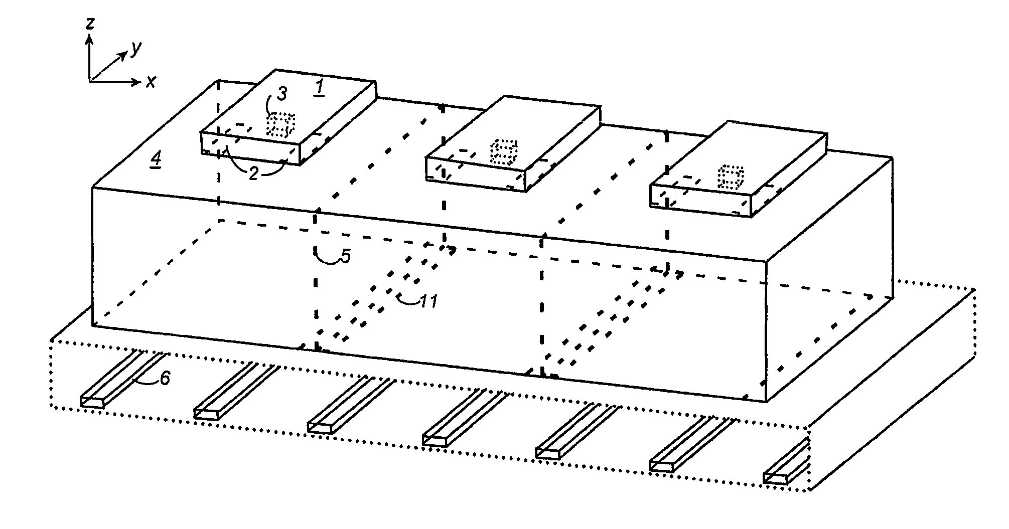
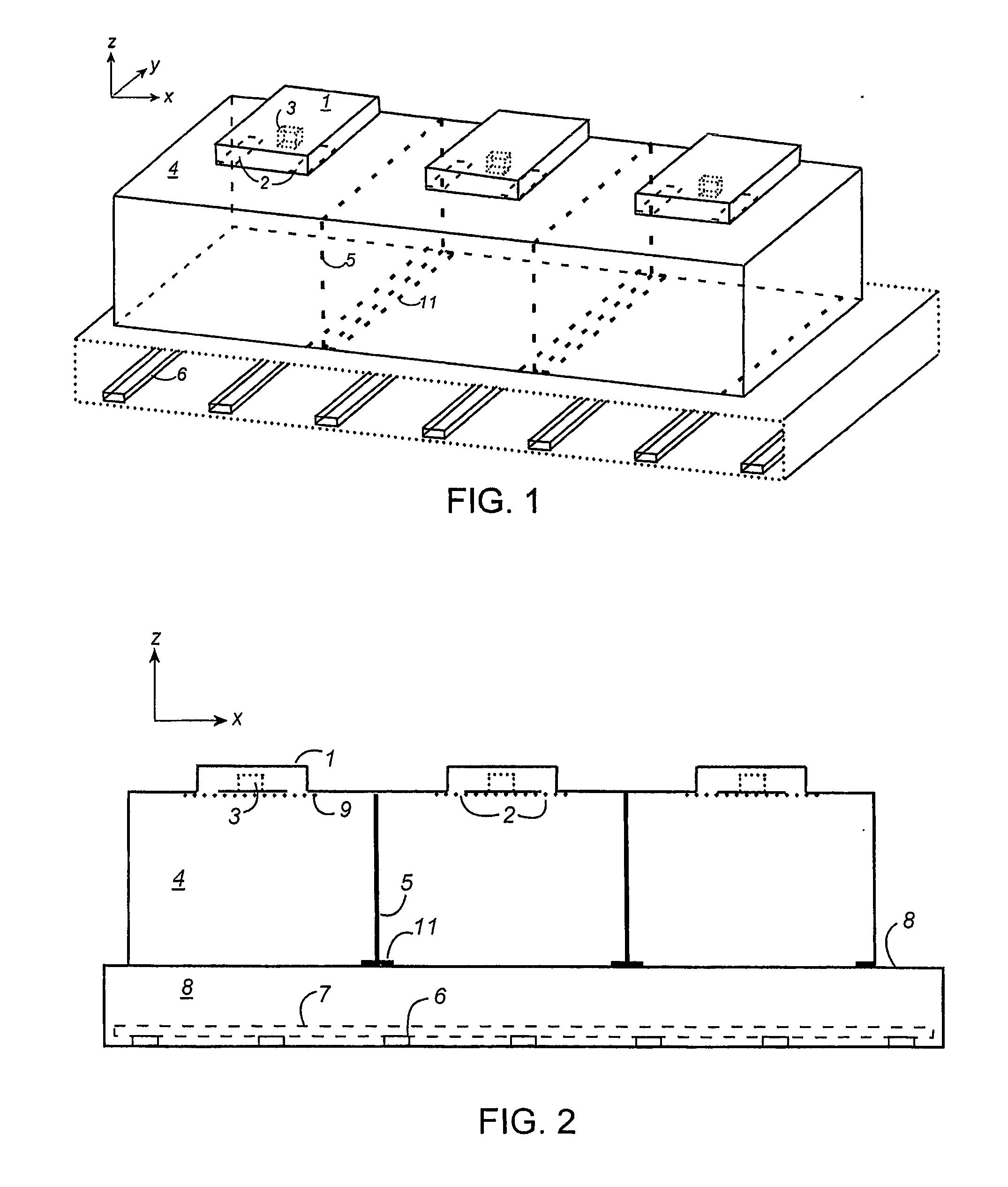
[0018] In one embodiment of the invention, the above effects are achieved by employing an evanescent TEy31 mode for the main power transferring mode, together with a propagating TEy11 mode for the second, counteracting mode. The excitation is then symmetrical around the center of the applicator ceiling in both the x- and y-directions. To excite these
modes, at least two parallel, y-directed excitation slots are required. Such excitation geometry will also eliminate the excitation of all TEynm
modes when either or both indices m and n are even. This feeding geometry is an advantageous, general feature of the invention, since the applicator may in some embodiments need to be larger in the x-direction (dimension a) than in the y-direction (dimension b), making it possible for the applicator to support such unwanted higher modes. More particularly, it is desired to have a weak x-directed H-field (especially at the applicator walls at y=0 and y=b), such that leakage of microwave energy in the tunnel below becomes low in the y-direction. Therefore, a / m should be small and b / n should be large, leading to the fact that the a-dimension of the applicator needs to be larger than the b-dimension for some selections of supported modes.
[0019] The excitation by means of two parallel slots connecting the applicator to a TE10 feeding
waveguide, the slots having an elongation along the wide side of the applicator and being located at the sides of the feeding
waveguide, results in the correct opposite polarity of the magnetic fields in the slots. In general, and for any type of feeding
waveguide, feeding of microwave energy into the applicator should be performed such that the H-fields along the slot are anti-parallel. In other words, feeding could also be accomplished by other types of waveguides, such as a TE11 or a TE20 waveguide, the TE10 type nevertheless being preferred.
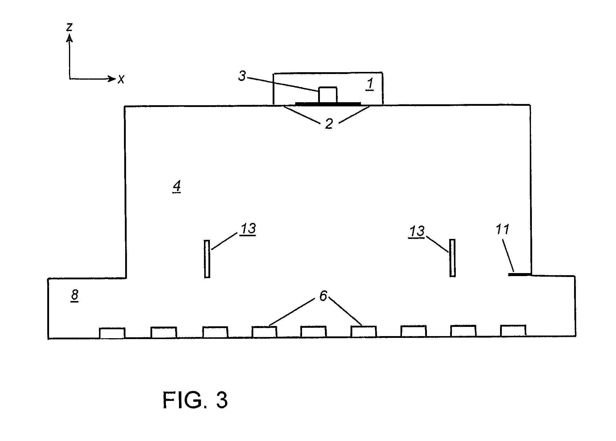
[0020] However, in order for the transition between the feeding TE10 waveguide and the applicator to also exhibit a good impedance transformation, it becomes theoretically and practically necessary to include reactive elements. In this context, it is preferred to add a quite large
metal post at the center-line of the TE10 waveguide, in a position halfway between the slots. This
impedance matching by means of a reactive element in the form of a
metal post centrally placed in the feeding waveguide is another useful feature of the invention.
[0021] When using a TEym;1 mode (where m=3, 5, 7, etc.) as the main power-transferring evanescent mode, the propagating complementary mode should in general be a TEym-2k;1 mode (where k=1, 2, 3, etc.). For example, when using the TEy51 mode (m=5) as the evanescent main power-transferring mode, the complementary propagating mode could be the TEy31 mode (k=1) or the TEy11 mode (k=2). For physical reasons, of course, no index can become negative. However, it becomes increasingly difficult to eliminate unwanted modes from the applicators when higher mode indices are used. In order to eliminate such unwanted modes, it is preferred to have mode filters in the form of two or more y-directed metal rods or plates extending all the way between opposite applicator walls. The correct positions for these rods or plates can be determined by experiment or by electromagnetic modeling. The aim is thereby to obtain equal strength for the y-directed elongated hot zones under the applicator, which dominantly characterize the heating pattern, plus another, weaker, elongated
hot zone just below each y-directed applicator side wall. The use of mode-discriminating bars or plates in the manner outlined above is another useful feature of the invention.
[0022] The major effect of unwanted LSM modes is that they create an x-directed propagation of energy, which is maintained also further sideways from the projection of the applicator opening on the metal plate (i.e. in the x-direction). The LSM mode or modes under the load is supported by x-directed currents in the metal plate below the belt and load. The unwanted propagation of these LSM modes beyond the desired limits can therefore be reduced if the x-directed current path in the metal plate is perturbed or interrupted. The preferred way of achieving this is to use a corrugated metal plate (where the corrugations are in the y-direction, i.e. in the direction of belt movement), or to
mount or
weld metal profiles on the plate which create a similar geometric conductor pattern. The varying height (the steps) of the plate cause changes in the x-directed impedance of the LSM mode, so that it is reflected mainly between adjacent steps. Again, the optimization of the metal plate corrugation pattern is preferably done by experiment and / or by electromagnetic modeling. The aim is then to obtain a good heating from below (i.e. to actually create an LSM mode) while minimizing spread-out in the x-direction from all sideways-mounted applicators. This use and optimization of the corrugations or the like is a further useful feature of the present invention.

