Eureka AIR delivers breakthrough ideas for toughest innovation challenges, trusted by R&D personnel around the world.

Liquid crystal display device and method of fabricating the same

a liquid crystal display and liquid crystal technology, applied in non-linear optics, instruments, optics, etc., can solve the problems of difficult control of the injection gravity failure, and difficulty in detecting the amount of liquid crystal material injection, so as to prevent touch brightness failure and prevent gravity failure

Inactive Publication Date: 2007-03-29
LG DISPLAY CO LTD
View PDF2 Cites 21 Cited by
  • Summary
  • Abstract
  • Description
  • Claims
  • Application Information

AI Technical Summary

Benefits of technology

[0009] An object of the present invention is to provide a liquid crystal display and a method of fabricating the same for preventing touch brightness failure in an LCD panel.
[0010] Another object of the present invention is to provide a liquid crystal display and a method of fabricating the same for preventing gravity failure in an LCD panel.

Problems solved by technology

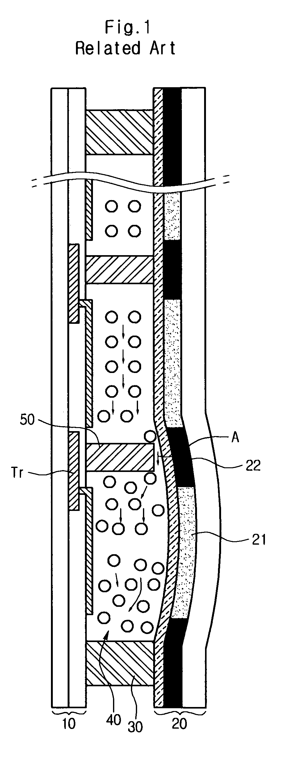
For instance, if the liquid crystal material is over-filled or expands due to high temperature, gravity failure may occur.
However, it is difficult to control the injection amount of the liquid crystal material.
Sometimes, the liquid crystal material may over-fill the inner space, which can result in a gravity failure.
Over-filling can cause other problems.
The non-uniform cell gap deteriorates the quality of the LCD and may cause a touch failure.
Gravity failure and the touch brightness failure become exacerbated as the screen size of the LCD increases.

Method used


Image

  • Liquid crystal display device and method of fabricating the same
  • Liquid crystal display device and method of fabricating the same
  • Liquid crystal display device and method of fabricating the same

Examples


Embodiment Construction

[0021] Reference will now be made in detail to the preferred embodiments of the present invention, examples of which are illustrated in the accompanying drawings. The invention can, however, be embodied in many different forms and should not be construed as being limited to the embodiments set forth herein; rather, these embodiments are provided so that this disclosure will be thorough and complete, and will fully convey the concept of the invention to those skilled in the art. In the drawings, the thicknesses of layers and regions are exaggerated for clarity. Like reference numerals in the drawings denote like elements.

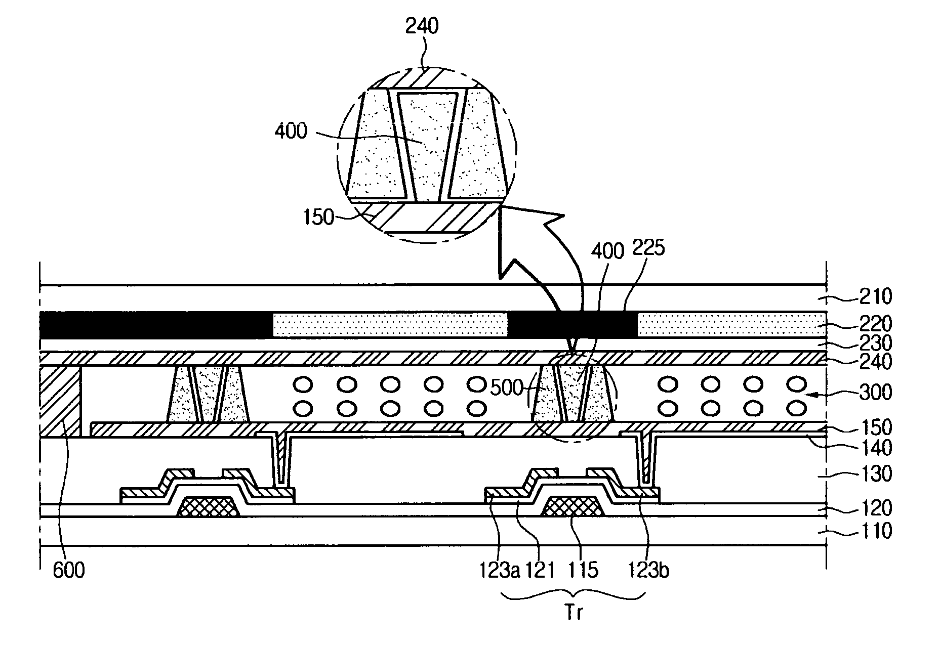
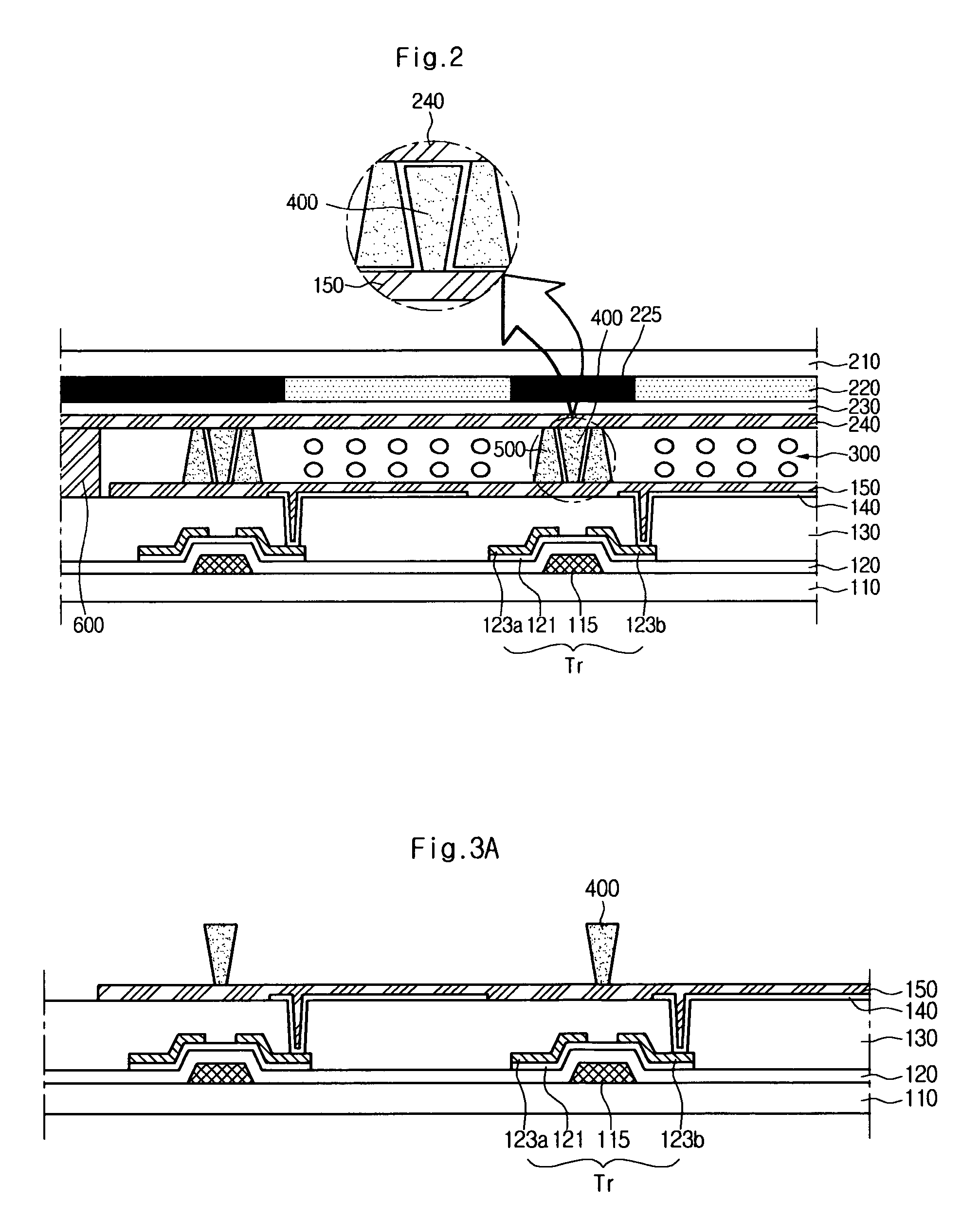
[0022]FIG. 2 is a cross-sectional view of an LCD according to an embodiment of the present invention. As shown in FIG. 2, the LCD includes a first substrate 110, a second substrate 210, and a liquid crystal layer interposed between the first and second substrates 110 and 210. The first substrate 110 has thin film transistors (Tr) and a first pattern spacer 400 forme...


PUM

PropertyMeasurementUnit
organicaaaaaaaaaa
shapeaaaaaaaaaa
electric fieldaaaaaaaaaa

Abstract

A liquid crystal display device includes: a first substrate having a plurality of gate lines and a plurality of data lines crossing each other; a second substrate facing the first substrate; a first pattern spacer having an inverse tapered shape on an inner surface of the first substrate; a second pattern spacer having an inverse tapered shape on an inner surface of the second substrate; a seal pattern on a peripheral edge of the first and second substrates; and a liquid crystal layer between the first and second substrates.

Description

[0001] The present invention claims the benefit of Korean Patent Application No. 090417 / 2005 filed in Korea on Sep. 28, 2005, which is hereby incorporated by reference in its entirety. BACKGROUND OF THE INVENTION [0002] 1. Field of the Invention [0003] The present invention relates to a display device, and more particularly, to a liquid crystal display device and a method of fabricating the same. [0004] 2. Description of the Related Art [0005] The liquid crystal display (LCD) device has been most favored recently as an efficient and value-added next generation display device, due to its low power consumption and its portability. In general, the LCD includes a lower substrate and an upper substrate arranged facing the lower substrate with a liquid crystal layer interposed between the lower substrate and the upper substrate. The lower substrate has a thin film transistor and a pixel electrode formed thereon. The upper substrate has a black matrix layer, a color filter layer and a comm...

Claims


Application Information

Patent Timeline
Patent Type & Authority Applications(United States)
IPC IPC(8): G02F1/1339
CPCG02F1/13394G02F1/1339
Inventor LEE, JOON SUKJEE, YOUNG SEUNGKIM, JEONG OH
Owner LG DISPLAY CO LTD
Why Eureka
Eureka Blog
Learn More